34
SYSTEM AREA
SW AUX OUTPUT
SWITCHED AUXILIARY
OUTPUT
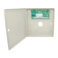
The switched auxiliary output terminal on the main panel is a 12 volt power supply activated and
deactivated by any one of 35 options. When the switched auxiliary is activated, it outputs 12 volts
(if measured, will read 13.8 volts). The switched auxiliary output, for some options can also be
programmed to activate for only selected partitions.
For example:
If the SW AUX output has been programmed for Sensor Reset and enabled on partition 1 and
partition 2.
Pressing [Q][4] on any keypad assigned to partition 1 or partition 2 will deactivate the output for
the amount time programmed in “PGM PULSE TIME”.
Pressing [Q][4] on a keypad assigned to partitions 3 and 4 will not activate the output.
Note: Refer to the PGM Outputs List for available options.
SW AUX OUTPUT
(05)
 Loading...
