Installation – Terminal Description
40
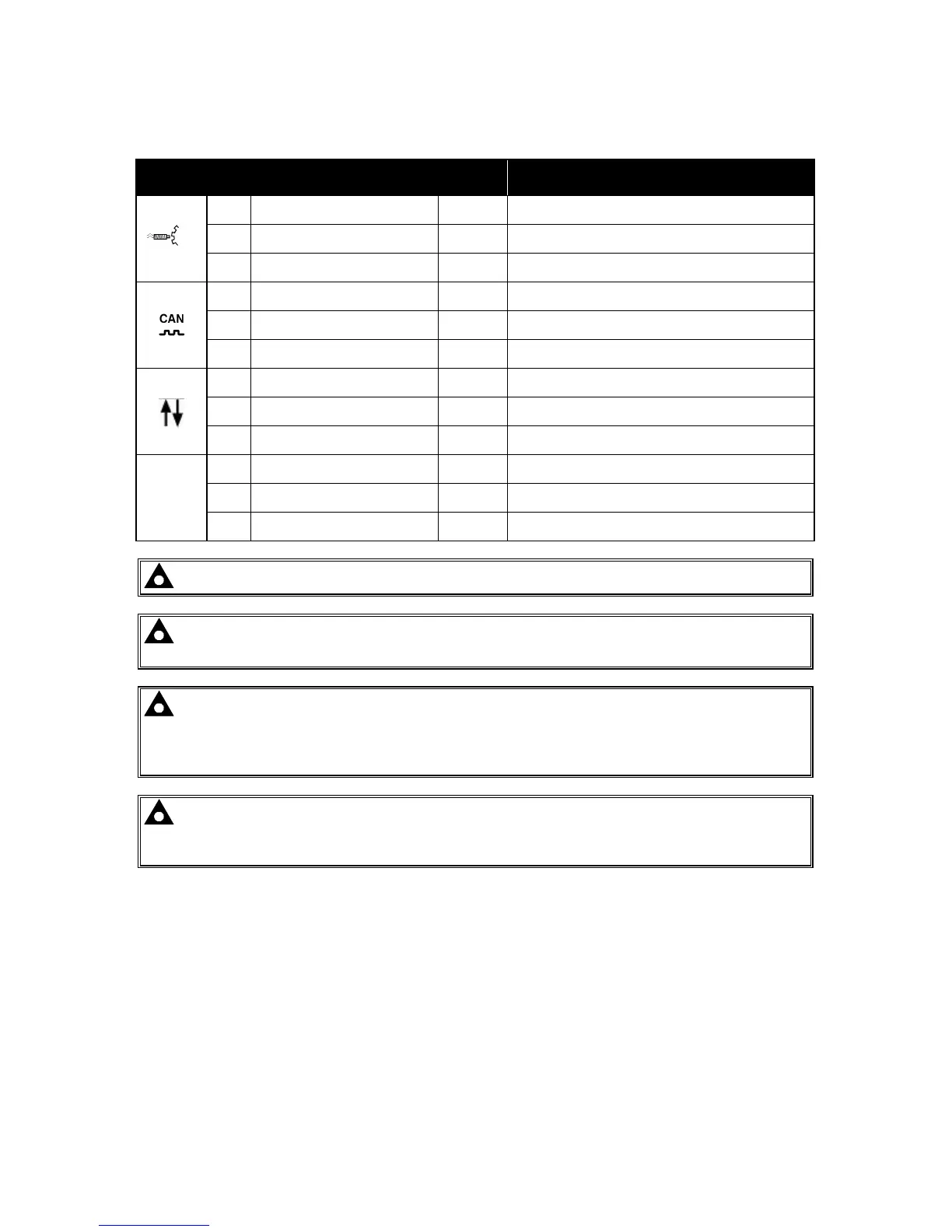
4.1.3 MAGNETIC PICKUP, CAN AND EXPANSION
PIN
No
DESCRIPTION CABLE
SIZE
NOTES
22 Magnetic pickup Positive
0.5mm²
AWG 20
Connect to Magnetic Pickup device
23 Magnetic pickup Negative
0.5mm²
AWG 20
Connect to Magnetic Pickup device
24 Magnetic pickup screen Shield Connect to ground at one end only
25 CAN port H
0.5mm²
AWG 20
Use only 120Ω CAN approved cable
26 CAN port L
0.5mm²
AWG 20
Use only 120Ω CAN approved cable
27 CAN port Common
0.5mm²
AWG 20
Use only 120Ω CAN approved cable
28 DSENet expansion +
0.5mm²
AWG 20
Use only 120Ω RS485 approved cable
29 DSENet expansion -
0.5mm²
AWG 20
Use only 120Ω RS485 approved cable
30 DSENet expansion SCR
0.5mm²
AWG 20
Use only 120Ω RS485 approved cable
MSC
31 Multiset Comms (MSC) Link H
0.5mm²
AWG 20
Use only 120Ω RS485 approved cable
32 Multiset Comms (MSC) Link L
0.5mm²
AWG 20
Use only 120Ω RS485 approved cable
33 Multiset Comms (MSC) Link SCR
0.5mm²
AWG 20
Use only 120Ω RS485 approved cable
NOTE:- Terminal 34 to 38 are not fitted to the controller
NOTE:- Screened cable must be used for connecting the Magnetic Pickup, ensuring that
the screen is earthed at one end ONLY.
NOTE:- Screened 120Ω
ΩΩ
Ω impedance cable specified for use with CAN must be used for the
CAN link and the Multiset comms link.
DSE stock and supply Belden cable 9841 which is a high quality 120Ω
ΩΩ
Ω impedance cable
suitable for CAN use (DSE part number 016-030)
NOTE:- When the module is configured for CAN operation, terminals 22, 23 & 24 should
be left unconnected. Engine speed is transmitted to the controller on the CAN link.
Refer to Electronic Engines and DSE Wiring for further information. Part No. 057-004.