Installation – Typical Wiring Diagrams
54
4.3.9 CT LOCATION
NOTE: CT Location is not applicable to the DSE7410 auto start controllers and is only
available in DSE7420 V1.3 .
There are two possible locations for the current transformers in the system:
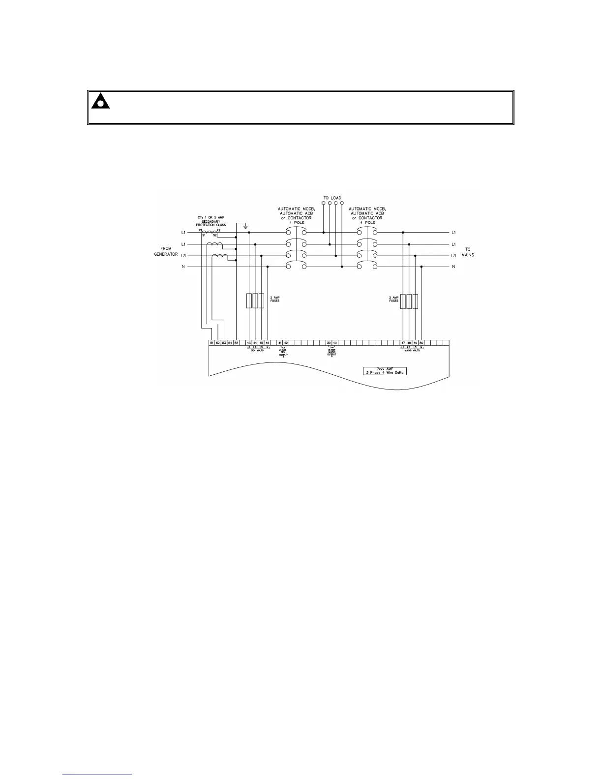
1) Generator: The CTs are used to measure and display generator current only. The typical wiring
diagrams in the preceding section all show the CT measuring the generator load. For clarity, an
example is shown below.
2) Load : The CTs are used to measure and display generator current when the generator is on load
and mains current when the mains is on load. The module display automatically changes to
display the current in the relevant instrumentation page. This example shows the CTs in the ‘load’
for a three phase delta system but the same philosophy is applicable to the other topologies.