Specification
11
3.5 GENERATOR CURRENT SENSING
Measurement type True RMS conversion
Sample Rate 5KHz or better
Harmonics Up to 10
or better
Nominal CT secondary rating 1A or 5A (5A recommended)
Maximum continuous current 5A
Overload Measurement 3 x Nominal Range setting
Absolute maximum overload 50A for 1 second
Burden
0.5VA (0.02Ω current shunts)
common mode offset ±2V peak plant ground to CT common terminal
Resolution 0.5% of 5A
Accuracy ±1% of Nominal (1A or 5A) (excluding CT error)
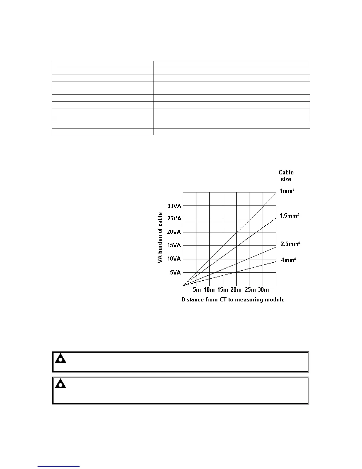
3.5.1 VA RATING OF THE CTS
The VA burden of the module on the CTs is 0.5VA. However depending upon the type and length of
cabling between the CTs and the module, CTs with a greater VA rating than the module are required.
The distance between the CTs and the
measuring module should be
estimated and cross-referenced
against the chart opposite to find the
VA burden of the cable itself.
If the CTs are fitted within the
alternator top box, the star point
(common) of the CTs should be
connected to system ground (earth) as
close as possible to the CTs. This
minimises the length of cable used to
connect the CTs to the DSE module.
Example.
If 1.5mm² cable is used and the
distance from the CT to the measurin
module is 20m, then the burden of the
cable alone is approximately 15VA. As
the burden of the DSE controller is
0.5VA, then a CT with a rating of at
least 15+0.5V = 15.5VA must be used.
If 2.5mm² cables are used over the
same distance of 20m, then the
burden of the cable on the CT is
approximately 7VA. CT’s required in
this instance is at least 7.5VA (7+0.5).
NOTE: - Details for 4mm² cables are shown for reference only. The connectors on the DSE
modules are only suitable for cables up to 2.5mm².
NOTE: - CTs with 5A secondary windings are recommended with DSE modules. 1A CTs
can be used if necessary however, the resolution of the readings is 5 times better when using
5A CTs.