Installation – Terminal Description
44
4.1.7 CONFIGURABLE DIGITAL INPUTS
PIN
No
DESCRIPTION CABLE
SIZE
NOTES
60 Configurable digital input A
0.5mm²
AWG 20
Switch to negative
61 Configurable digital input B
0.5mm²
AWG 20
Switch to negative
62 Configurable digital input C
0.5mm²
AWG 20
Switch to negative
63 Configurable digital input D
0.5mm²
AWG 20
Switch to negative
64 Configurable digital input E
0.5mm²
AWG 20
Switch to negative
65 Configurable digital input F
0.5mm²
AWG 20
Switch to negative
66 Configurable digital input G
0.5mm²
AWG 20
Switch to negative
67 Configurable digital input H
0.5mm²
AWG 20
Switch to negative
68 Configurable digital input I
0.5mm²
AWG 20
Switch to negative
69 Configurable digital input J
0.5mm²
AWG 20
Switch to negative
70 Configurable digital input K
0.5mm²
AWG 20
Switch to negative
NOTE:- See the software manual for full range of configurable outputs available.
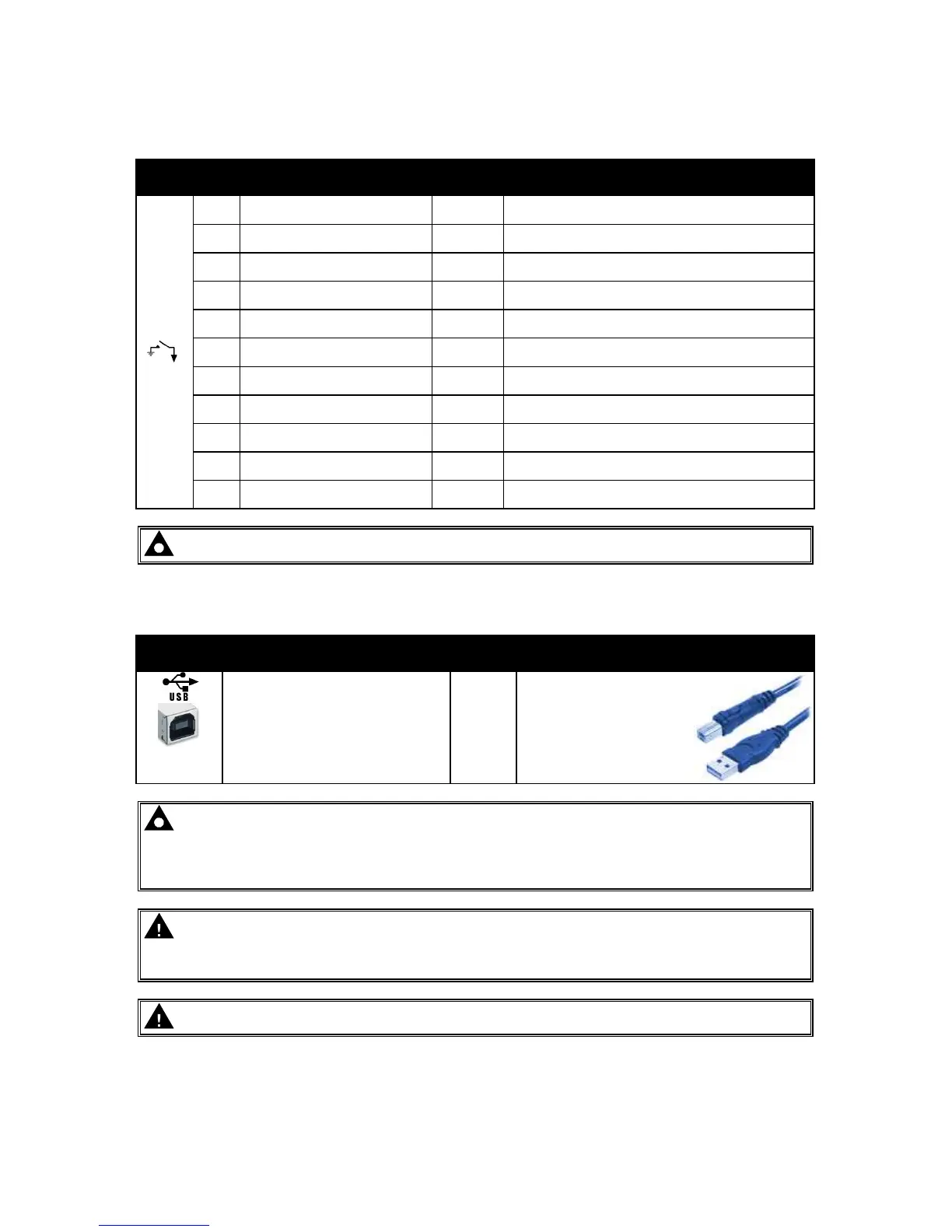
4.1.8 PC CONFIGURATION INTERFACE CONNECTOR
DESCRIPTION CABLE
SIZE
NOTES
Socket for connection to PC
with DSE Configuration Suite
Software
0.5mm²
AWG 20
This is a standard USB
type A to type B
connector.
NOTE:- The USB connection cable between the PC and the module must not be extended
beyond 5m (yards). For distances over 5m, it is possible to use a third party USB extender.
Typically, they extend USB up to 50m (yards). The supply and support of this type of
equipment is outside the scope of Deep Sea Electronics PLC.
CAUTION!: Care must be taken not to overload the PCs USB system by connecting more
than the recommended number of USB devices to the PC. For further information, consult
your PC supplier.
CAUTION!: This socket must not be used for any other purpose.