Installation – Terminal Description
41
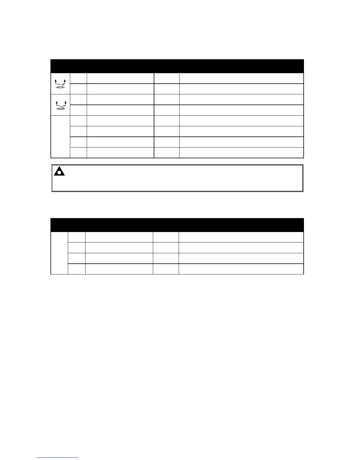
4.1.4 LOAD SWITCHING AND V1 GENERATOR VOLTAGE SENSING
PIN
No
DESCRIPTION CABLE
SIZE
NOTES
39 Output relay C
1.0mm
AWG 18
Normally configured to control mains contactor coil
(Recommend 10A fuse)
40 Output relay C
1.0mm
AWG 18
Normally configured to control mains contactor coil
41 Output relay D
1.0mm
AWG 18
Normally configured to control generator contactor coil
(Recommend 10A fuse)
42 Output relay D
1.0mm
AWG 18
Normally configured to control generator contactor coil
V1
43
Generator L1 (U) voltage
monitoring
1.0mm²
AWG 18
Connect to generator L1 (U) output (AC)
(Recommend 2A fuse)
44
Generator L2 (V) voltage
monitoring input
1.0mm²
AWG 18
Connect to generator L2 (V) output (AC)
(Recommend 2A fuse)
45
Generator L3 (W) voltage
monitoring input
1.0mm²
AWG 18
Connect to generator L3 (W) output (AC)
(Recommend 2A fuse)
46 Generator Neutral (N) input
1.0mm²
AWG 18
Connect to generator Neutral terminal (AC)
NOTE:- The above table describes connections to a three phase, four wire alternator. For
alternative wiring topologies, please see the ALTERNATIVE AC TOPOLOGIES section of this
manual.
4.1.5 V2 BUS/MAINS VOLTAGE SENSING
PIN
No
DESCRIPTION CABLE
SIZE
NOTES
V2
47
Bus/Mains L1 (R) voltage
monitoring
1.0mm
AWG 18
Connect to Mains L1 (R) incoming supply (AC)
(Recommend 2A fuse)
48
Bus/Mains L2 (S) voltage
monitoring
1.0mm
AWG 18
Connect to Mains L1 (S) incoming supply (AC)
(Recommend 2A fuse)
49
Bus/Mains L3 (T) voltage
monitoring
1.0mm
AWG 18
Connect to Mains L1 (T) incoming supply (AC)
(Recommend 2A fuse)
50 Bus/Mains Neutral (N) input
1.0mm
AWG 18
Connect to Mains N incoming supply (AC)