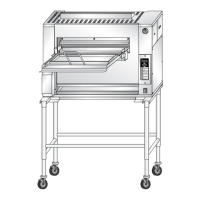
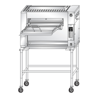
Service Manual for Flexible Batch Broiler Units
28
Testing the Conveyor Drive Motor
The Conveyor Drive Motor may be tested without
removing it from the broiler.
WARNING
DISCONNECT THE ELECTRICAL
POWER TO THE BROILER AND
FOLLOW LOCKOUT / TAGOUT
PROCEDURES.
1. Turn off and disconnect the broiler.
2. Remove the Conveyor Drive Motor Cover.
3. Tag and disconnect the wires.
4. Use an Ohmmeter to measure resistance.
5. Attempt to run the Drive Motor when it’s
disengaged from the Drive Chain.
NORMAL MOTOR RESISTANCE (230 VAC, 60 HZ)
Wires to Test Resistance
Black and Brown 98.1 Ω
Black and Orange 98.1 Ω
Brown and Orange 196.2 Ω
Checking Conveyor Drive Motor Capacitor
If the motor tests OK, check the Capacitor. The
Capacitor is located in the service area on the
control side of the broiler.
WARNING
DISCONNECT THE ELECTRICAL
POWER TO THE BROILER AND
FOLLOW LOCKOUT / TAGOUT
PROCEDURES.
1. Remove the Electrical Access Panel. Refer
to the COVERS and PANELS section of the
manual.
2. Disconnect the wires connected to the
Capacitor.
3. Discharge the Capacitor by shorting both
terminals to ground at the same time.
4. Use an Ohmmeter to test the Capacitor.
NOTE: If both the Drive Motor and Capacitor
test OK, the problem is probably with the Drive
Motor Relay.
Testing the Relays
There are seven Solid-State Relays in the broiler.
Six control the Heating Elements, while the other
controls the Conveyor Drive Motor.
WARNING
DISCONNECT THE ELECTRICAL
POWER TO THE BROILER AND
FOLLOW LOCKOUT / TAGOUT
PROCEDURES.
1. Remove the Electrical Access Panel. Refer
to the COVERS and PANELS section of the
manual.
2. Turn ON the Main Power Switch.
3. The Heating Elements are energized when
the Controller calls for heat. To test the relay,
check for voltage on the input of the relay. See
the chart below. At the same time, monitor
AC current to Heating Elements. When no
relay input voltage is present, there will be no
amperage draw on the output of the relay.
NOTE: (SSR4) is unique and operates with
a DC voltage input
Relay #
Input
Voltage
Range
Typical
Voltage
Reading
Max.
Output
Amps
SSR1 18-36 VAC 24 VAC 50 A
SSR2 18-36 VAC 24 VAC 50 A
SSR3 18-36 VAC 24 VAC 50 A
SSR4 4-32 VDC 6 VDC 50 A
SSR5 18-36 VAC 24 VAC 50 A
SSR6 18-36 VAC 24 VAC 50 A