29
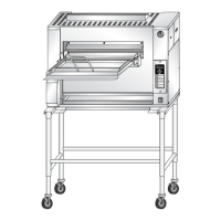
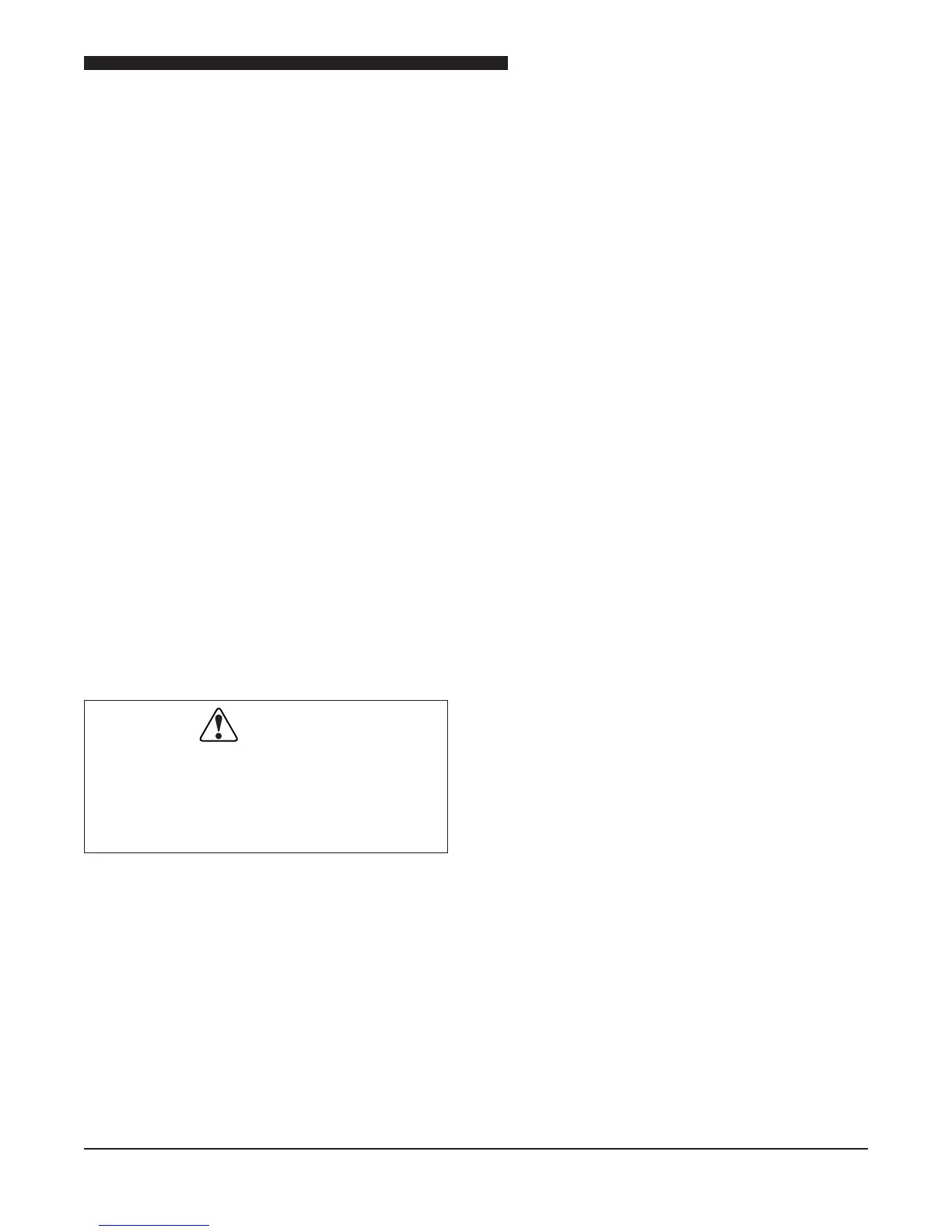
Service Manual for Flexible Batch Broiler Units
The Conveyor Drive Motor runs when the Drive
Motor Relay is energized by the Control.
The Solid State Relay that controls the Conveyor
Drive Motor, utilizes a 4.5 - 32 VDC (typically 6
VDC) input signal to switch up to 10A on the output.
TESTING THE TRANSFORMERS
The 24-volt Step-Down Transformer in the broiler
supplies power to the Control Board. Either a
voltage or a resistance check can be used to test
the Transformer.
Voltage Test
1. Make sure the broiler is turned OFF.
2. Remove the Electrical Access Panel. Refer
to the COVERS and PANELS section of the
manual.
3. Disconnect the secondary winding.
4. Turn the broiler on.
5. Using a VOM, test the voltage output across
the secondary winding. Voltage should be
24 VAC.
Resistance Check
WARNING
DISCONNECT THE ELECTRICAL
POWER TO THE BROILER AND
FOLLOW LOCKOUT / TAGOUT
PROCEDURES.
1. Turn the broiler OFF.
2. Remove the Electrical Access Panel. Refer
to the COVERS and PANELS section of the
manual.
3. Tag and disconnect the wires of the Transformer
to be tested.
4. Measure the resistance across the primary.
Primary Resistance = 71.5 Ω ±10%.
5. Measure resistance across secondary.
6. Secondary Resistance = 1.3 Ω ±10%.
TESTING THE MECHANICAL RELAYS
The two Mechanical Relays work in conjunction
with the safety interlocks to allow safe access to
the various areas of the Broiler.
When working properly, they allow AC input voltage
to the two Contactors, which allow the elements
to heat.
Continuity Test
1. Make sure broiler is turned OFF.
2. Remove the Electrical Access Panel. Refer
to the COVERS and PANELS section of the
manual.
3. Disconnect a single contact terminal on the
Mechanical Relay and tape off for safety.
4. Turn the broiler on.
5. Test continuity across the two contact
terminals. With Safety Interlock panels
installed, continuity should be present.
TESTING THE CONTACTORS
The two Contactors in the broiler lie in series with
each other and supply power to the Elements.
Voltage Test
1. Make sure the broiler is turned OFF.
2. Remove the Electrical Access Panel. Refer
to the COVERS and PANELS section of the
manual.
3. Turn the broiler on.
4. Visually validate that the Contactor is energizing
and “pulling in”.
5. If Contactor does not energize, ensure
208/240 VAC is present at the input coil.