9000X AF Drives User Manual
MN04001004E
For more information visit: www.eaton.com 3-5
June 2009
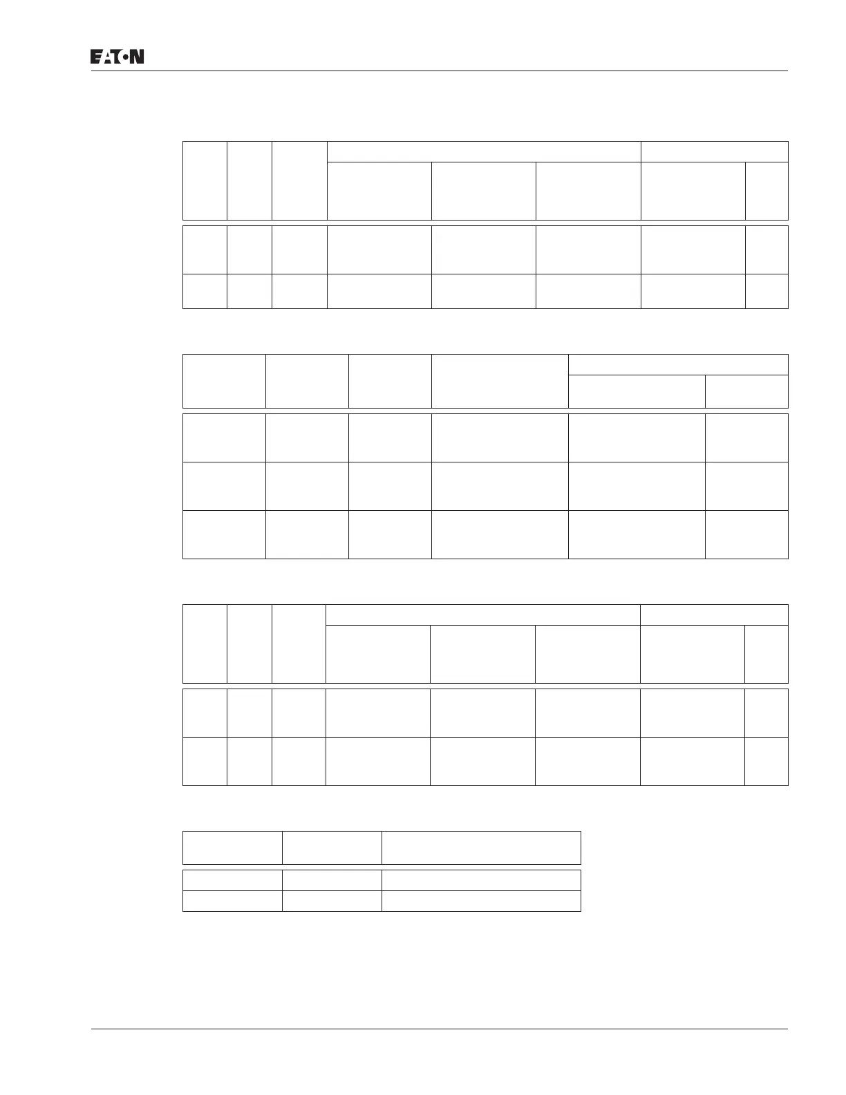
Table 3-6: Cable and Busbar Sizes, SPX FR13 – FR14 — 480V Ratings
Rigid copper connection.
Table 3-7: Cable and Busbar Sizes, SPX FR10 – FR12 — 575V Ratings
90°C rating recommended.
Table 3-8: Cable and Busbar Sizes, SPX FR13 – FR14 — 575V Ratings
Rigid copper connection.
Table 3-9: Maximum Symmetrical Supply Current
hp
Frame
Size Current
Internal Power Connections Supply Busbars
Busbar Size
NFE – INU
(in Inches)
Busbar Size/
Phase
(Choke — NFE)
(in Inches)
Cable Size/
Phase
(Choke — NFE)
Cu
(in Inches) Qty.
800
900
1000
FR13 1030
1150
1300
2.36 x 0.39
3.15 x 0.39
3.15 x 0.39
1.57 x 0.25
1.57 x 0.25
1.57 x 0.25
2 x 300 MCM
2 x 250 MCM
2 x 250 MCM
1.57 x 0.25
1.57 x 0.25
1.57 x 0.25
6
12
12
1200
1600
FR14 1600
1940
2.36 x 0.39
2.36 x 0.39
1.57 x 0.25
1.57 x 0.25
2 x 250 MCM
2 x 300 MCM
1.57 x 0.25
1.57 x 0.25
12
12
hp
Frame
Size
Current
Internal Power Cables
Cu (per phase)
External Power Busbars
Cu
(in Inches) Qty.
200
250
300
FR10 208
261
325
2x2/0
2x2/0
2x2/0
1.18 x .25
1.18 x .25
1.18 x .25
3
3
3
400
450
500
FR11 385
460
502
2x3/0
2x3/0
2x2x2/0
1.57 x .25
1.57 x .25
1.18 x .25
3
3
6
—
600
700
FR12 590
650
750
2x2x2/0
2x2x2/0
2\x2x2/0
1.18 x .25
1.18 x .25
1.18 x .25
6
6
6
hp
Frame
Size Current
Internal Power Connections Supply Busbars
Busbar Size
NFE – INU
(in Inches)
Busbar Size/
Phase
(Choke — NFE)
(in Inches)
Cable Size/
Phase
(Choke — NFE)
Cu
(in Inches) Qty.
800
900
1000
FR13 820
920
1030
2.36 x 0.39
2.36 x 0.39
2.36 x 0.39
1.57 x .25
1.57 x .25
1.57 x .25
2 x 300 MCM
2 x 250 MCM
2 x 300 MCM
1.18 x .25
1.18 x .25
1.18 x .25
6
6
6
1350
1500
2000
FR14 1300
1500
1900
3.15 x 0.39
2.36 x 0.39
2.36 x 0.39
1.57 x .25
1.57 x .25
1.57 x .25
2 x 250 MCM
2 x 250 MCM
2 x 300 MCM
1.18 x .25
1.18 x .25
1.18 x .25
12
12
12
Product Voltage
Maximum RMS Symmetrical
Amperes on Supply Circuit
3/4 – 30 hp 230 100,000A
1-1/2 – 200 hp 480 100,000A
 Loading...


