34
Manual CEAG CG-Controller for CG 2000/ZB-S 30080001458 (C) July 2016 www.ceag.de
11 LED displays
11 LED displays
11.1 LED indicators
“Ready for operation”
“Test mode” and “Failure”
11.1. 1 Control module (LED displays)
11.1.1.1 Ready for o peration
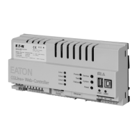
The front plate of the CG-Controller shows the
“Ready for operation” state with a green LED.
• LED green on = The entire „Emergency
lighting“ system is ready for
operation.
11.1.1.2 Test mode
The front plate of the CG-Controller shows the
“Test mode” state with a yellow LED.
• LED yellow on = One or more emergency
lighting systems arein test
mode.
11.1.1.3 Failure
The “Failure” status is indicated by a red LED.
• LED red on = One or more emergency
lighting systems are reporting
a failure.
12 Secure-Digital-Memory
Card SD
12.1 Device configurations
12.1.1 Configuring devices
withSD
You can use the «Setup device» / «Dev. config.
← SD» menu item to configure devices.
This configuration can then be transferred to the
devices with the Secure-Digital-Memory Card
SD (see Figure 2).
12.1.2 Reading the device config-
uration and saving to SD
You can use the «Setup device» / «Dev.
config. → SD» menu item to save the device
configuration to the Secure-Digital-Memory
Card (see Figure 3).
12.2 Logbook
Logbook entries are retrieved by the system on
a regular basis. Entries that are read are saved
on the SD of the CG controller.
If no SD is plugged in, the logbook is located in
EPROM.
Table 5: LED indicators
No:
1
2
3
4
5
6
7
8
9
10
11
12
13
14
15
16
17
One or more
emergency lighting systems
Manual reset
Functiontest
Durationtest
Deep discharge protection
Block
Operation
Mains failure of UV S3/S4
Mains failure of UV RS485
Mains failure of device
RS485 transmission fault
Battery failure
Converter failure
Charge-/isol. failure
Luminaire failure
Not enough capacity
Battery operation
CG-S bus communication failure
Ready for operation
LED green on
X
X
X
X
X
X
Test mode
LED yellow on
X
X
Failure
LED red on
X
X
X
X
X
X
X
X
X
X
X
X
X
X

 Loading...


