10/10 MN05003003Z-EN
Connecting a pulse
transmitter/incremental
encoder
23
Connecting a pulse transmitter/incremental encoder
Inputs I1 to I4 are designed so that high-speed signals from pulse
transmitters/incremental encoders can be counted.
The following connection options are possible:
•1 x pulse transmitters (32-bit)
•2 x pulse transmitters (16-bit)
•1 x incremental encoder (32-bit).
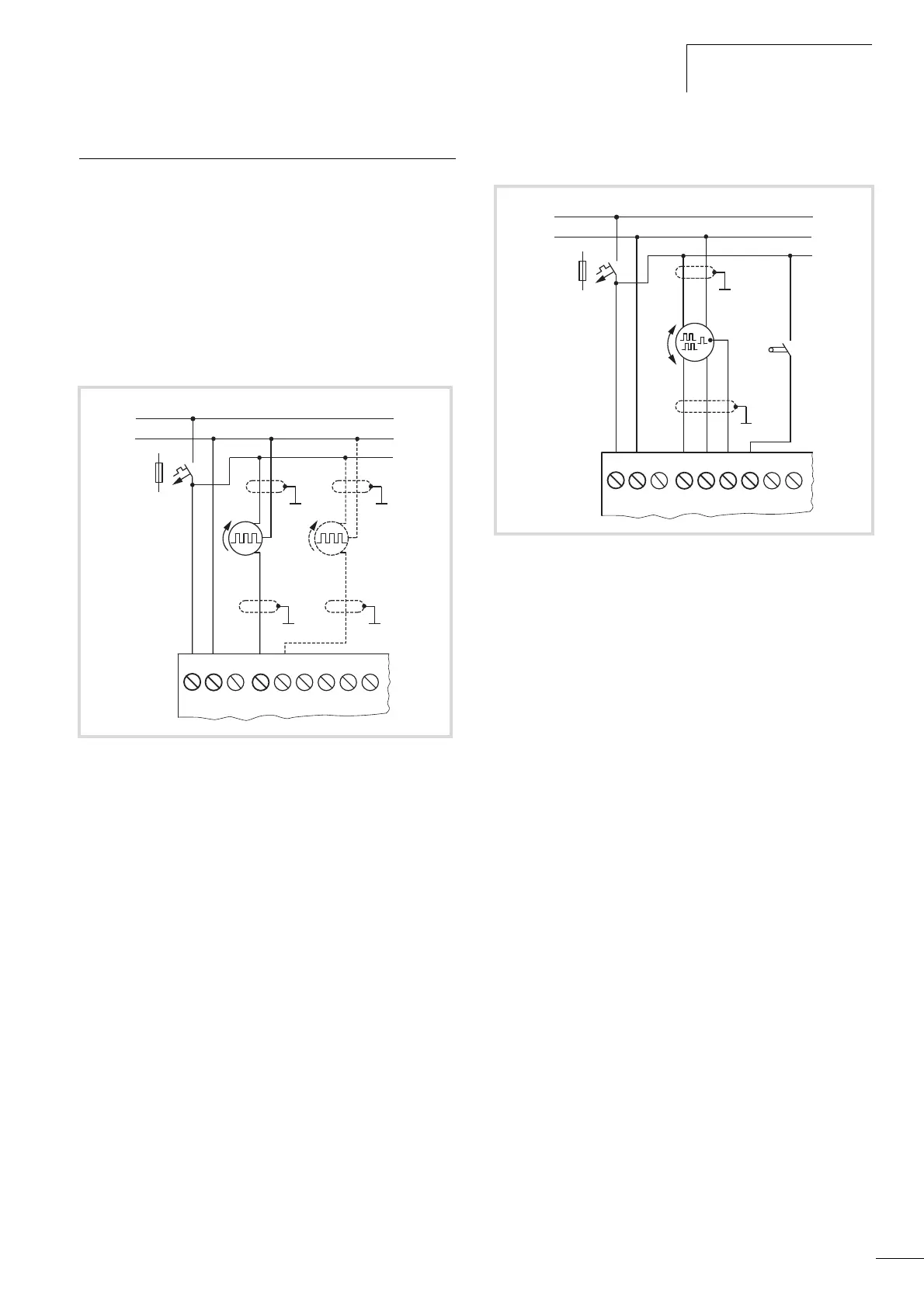
Connecting pulse transmitter
The figure shows the connection of a pulse transmitter which
sends pulses to input I1. An internal counter processes the pulses.
You can choose between a 16-bit counter (max. 65535) and 32-bit
counter (max. 4294967295). The pulse transmitter for the 32-bit
counter must only be connected to I1. Only if a 16-bit counter was
used at I1, can another pulse transmitter (32-bit) be connected to
I2.
Connecting the incremental encoder
Figure 22: Connecting pulse transmitter
0 V
0 V
...V
L01 –
F1
L01 +
I1
I2 I3
I4 I5
I6
L02 +
24 V H
Figure 23: Connecting the incremental value encoder
A, B: square-wave incremental signals that have a 90 degree phase shift
C: Reference signal
K1: Reference window switch
0 V
0 V
...V
L01 –
F1
L01 +
I1
I2 I3
I4 I5
I6
L02 +
AB
24 V H
C
K1

 Loading...


