10/10 MN05003003Z-EN
Description of important
functions / function blocks
81
Example of text and values output
(with the Disp_DisplayElement FB) The display is required to
display the values of the variables “motor1” and “motor2”.
The two values are changed continuously by the user program.
Operations via the PLC inputs
– I1 = FALSE: Status display
– I1 = TRUE: Entry/output mode
– I2 = FALSE: ESC button active
– I2 = TRUE: ESC button disabled
– I3 = TRUE: The first line is shown on the display.
– I5 = TRUE: The third line is shown on the display.
Execution
The example program consists of programs:
• STARTPROGRAM
– The “startprogram” is called on system event “Start”.
– The auxiliary variable g_xFirstCycleAfterStartProgram is set.
•PLC_PRG
– 2 values are incremented.
– The program “Visualisation” is called.
• VISUALISATION
– Registering and positioning of variables on the display in
the first cycle
– The auxiliary variable g_xFirstCycleAfterStartProgram is
reset.
– Activation of Entry/output mode (I1)
Start display (I3,I5)
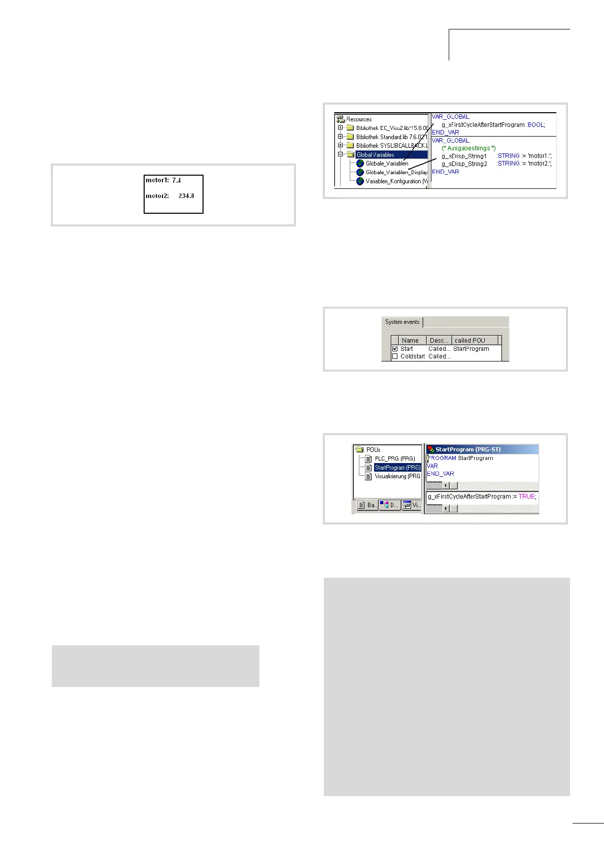
Declare variables
X First declare for each text element that you wish to display, such
as “motor1”, a variable of type “String” in the
“Global_Variables_Display” list as shown in the following
example (see alsofigure 95):
Creating auxiliary variables
X For the first program cycle call “Startprogram” on system event
“Start”.
X Set an auxiliary variable “g_xFirstCycleAfterStartProgram” in
this program that you reset after the first cycle is completed.
The auxiliary variable must be declared globally a figure 95.
Creating the program “StartProgram”
X Write the program “StartProgram” as in a figure 97.
Creating the “PLC_PRG” program
Figure 94: Example of text and values output
VAR GLOBAL
g_sDisp_String1 :STRING:='Motor1';
END_VAR
Figure 95: Declaration of display variables
Figure 96: Defining the system event
Figure 97: Creating the “startprogram”
PROGRAM PLC_PRG
VAR
fbTimer1 :TON;
(* Display values of the application
*)
byValue :BYTE;
wValue :WORD;
END_VAR
-----------------------------------------------------------
fbTimer1(IN:=NOT fbTimer1.Q , PT:=t#50ms );
IF fbTimer1.Q = TRUE THEN
byValue := byValue + 1;
wValue := wValue + 1;
END_IF
Visualisation(); (* Call visualisation *)

 Loading...


