Programming:via a CANopen
network (Routing)
10/10 MN05003003Z-EN
72
Example: Accessing a PLC program
The example below illustrates the procedure for accessing a PLC
program.
You have connected the PC to the PLC with node ID 2 and want to
access the target PLC with routing ID 54.
X Open the project of the target PLC (Node ID 3) whose program
you wish to edit or test.
X First configure the parameters for the hardware connection PC
n PLC (Node ID 2).
X From the Online menu select Communication Parameters...
X Click the New button under “local” channels.
The “New Channel” window appears.
X Select the channel in the “Device” window:
Serial [RS232] [Level 2 Route] or TCP/IP [Level 2 Route].
X You can assign a new name in the Name field, e.g.
"Rout_232".
You have now defined the parameters for the hardware
connection between the PC and the PLC (node ID 2).
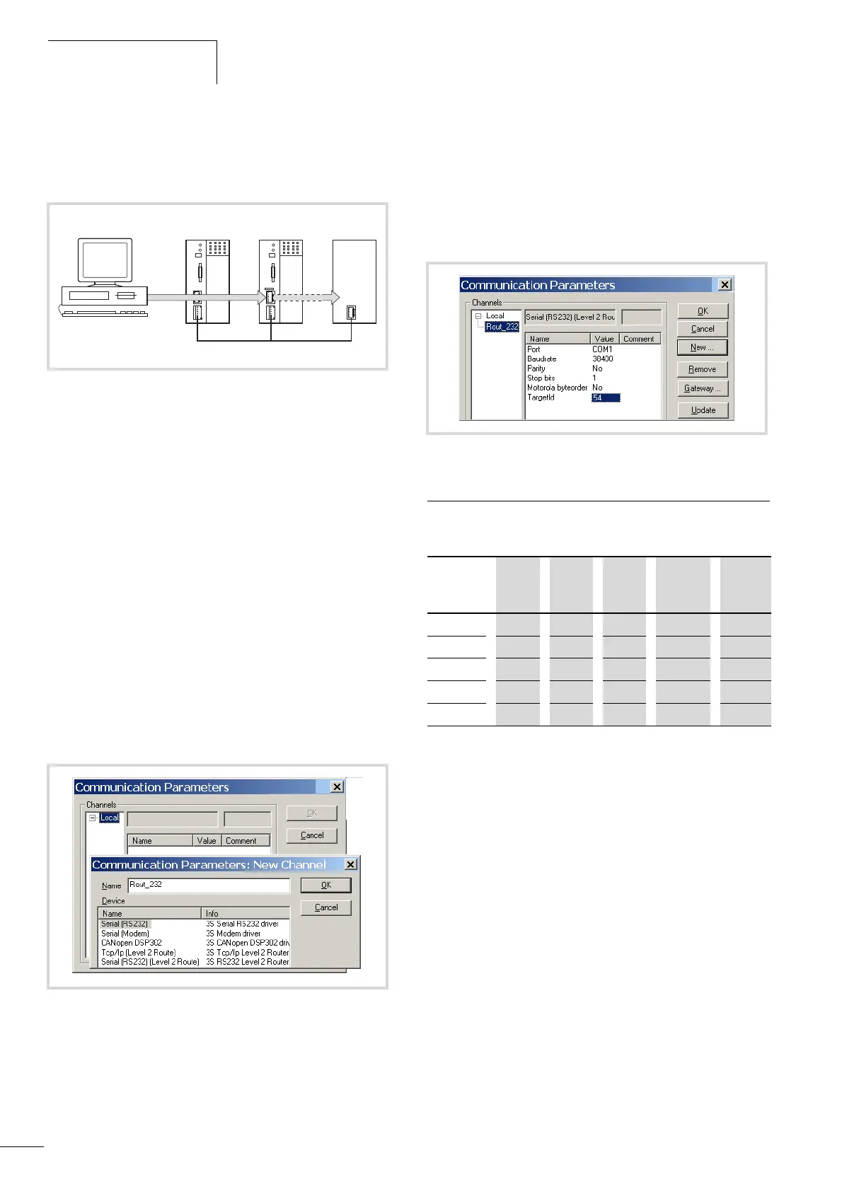
X Enter the target ID of the target station, number 54 in the
example. The target ID is identical to the routing ID!
To enter the target ID, click on the field in the Value column, to
the right of the term Target ID. Enter the number 54 there and
confirm with OK.
X Log on and carry out the action.
PLC combinations for routing
The following PLC support routing:
Figure 88: Diagnostics possibilities
a XC100 with Node ID 1
b XC200 with node ID 2, routing ID 127
c Controller with the node ID 3 and routing ID 54
(e.g. XC100, XC200, XC121, EC4-200)
Figure 89: Channel parameter setting
Figure 90: Setting the target ID of the target PLC
From P
XC100 XC121 XC200 EC4-200 MFD4
To O
XC100 x x x x x
XC121
x x x x x
XC200
x x x x x
MFD4
x x x x x
EC4-200
x x x x x

 Loading...


