GENERATOR OPERATION
The attached generator can only be started when the grid is lost, and the generator is wired for 2-wire
stop/start using the “Dry 1” contacts on the communications board. The internal grid relay and the
internal generator relay cannot be closed at the same time to ensure generator output does not send
power to the grid.
The GridBOSS should use start/stop relay 1 in the normally open connection. Start/stop relay 1 can be
controlled manually or by battery SOC/voltage logic within the EG4
®
Monitor Center. The generator can
also be configured with warm-up, cool-down, and exercise time.
The GridBOSS generator relay can only be closed after the start/stop relay 1 is closed. When start/stop
relay 1 is closed, the GridBOSS must wait until the generator can supply stable output power. This wait
time is configured using the generator warm-up time setting in the EG4
®
Monitor Center. Once the
generator warm-up time is complete, the GridBOSS will close the generator relay. Before the generator
can be safely powered off, the generator must complete the cool-down time. Once the cool-down time
is complete, the GridBOSS will open the generator relay and start/stop relay 1. The Start/Stop relay 1
connection is labeled Dry 1 on the GridBOSS cover plate. The Dry 2 connections are currently unused
and reserved for future use.
Generator 2-Wire Start Specifications
• Maximum Voltage 30VDC, 277VAC
• Maximum NO Contact Current: 5A
• Maximum NC Contact Current: 3A
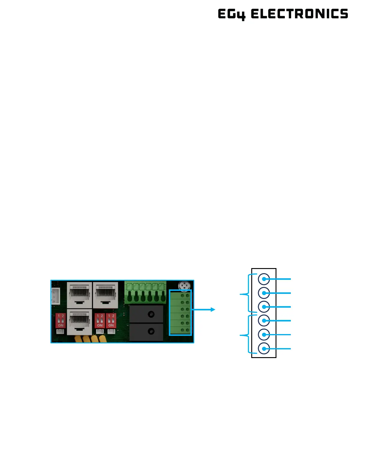
GridBOSS Communications Board
• COM1 and NC1 are a set of normally closed switches
• COM1 and NO1 are a set of normally open switches
• COM2 and NC2 are a set of normally closed switches
• COM2 and NO2 are a set of normally open switches