6.7 CONFIGURE GRIDBOSS
Before configuring the GridBOSS, verify the following:
• The inverter(s) are fully configured with at least the minimum firmware required to operate
with the GridBOSS. This should have been completed in the previous section.
• Each hybrid inverter is powered off.
• All GridBOSS breakers are in the off position.
• If a main breaker is not installed in the GridBOSS, verify that the source providing power to
the GridBOSS is in the off position.
• If the non-backup port is connected to an electrical panel, verify that the breaker in that panel
is in the off position. DO NOT switch on the electrical panel main breaker until the GridBOSS
is completely configured.
• Before proceeding with the steps below, use a multimeter to verify that there is no
voltage/current present at each GridBOSS lug and breaker.
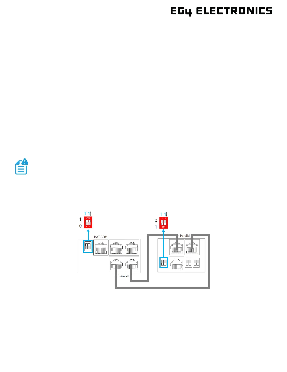
1. Connect the communication cable between the GridBOSS and the inverter(s) using the images
below as reference. The GridBOSS DIP switches should remain in the down position (ON) as
shipped from the factory. Also, note that the GridBOSS DIP switch On and Off positions are
flipped 180 degrees compared to the inverters.
If the communications cable needs to be replaced or a longer cable is required,
use a CAT5 or higher specification straight-through network cable in the 568B
format. The communications cable cannot be longer than 260 feet (80 meters).
GridBOSS with One Hybrid Inverter