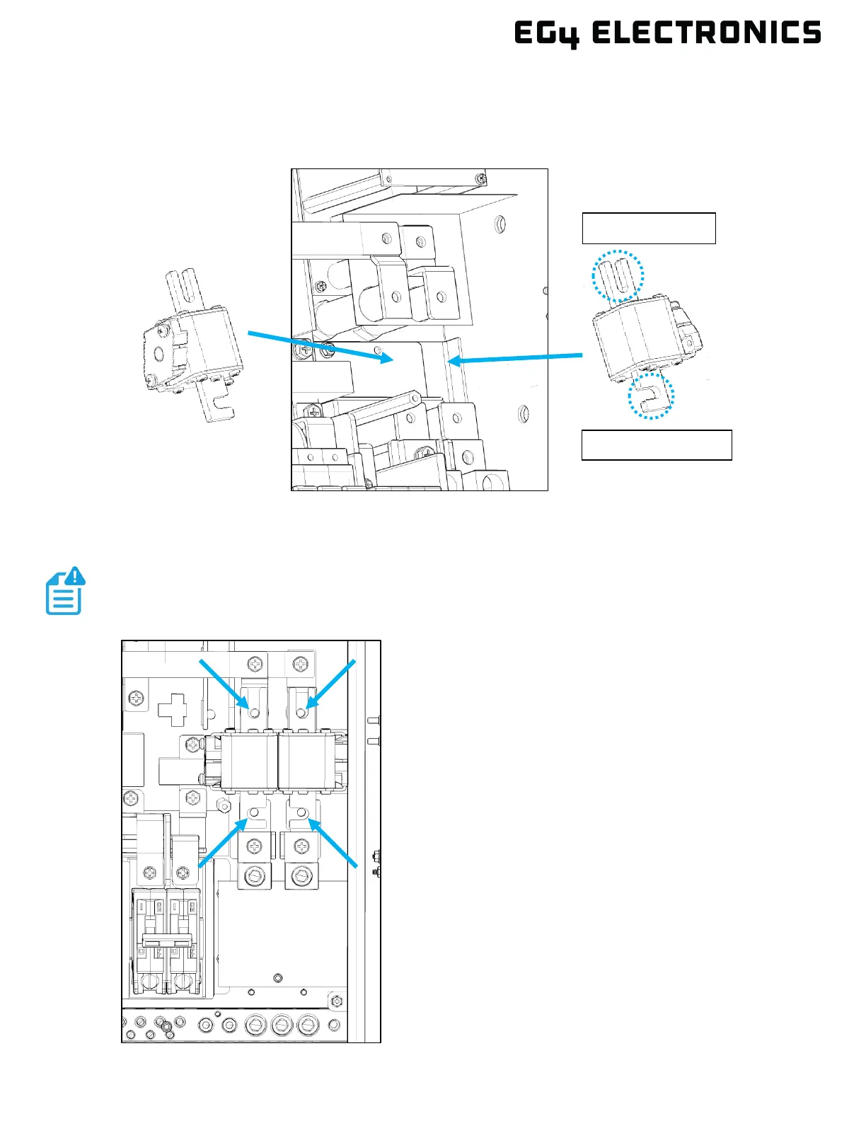
5. Set the new fuse in place. Verify that the direction of the fuse matches the image below. The
smaller notch open to the side should be towards the grid input, and the longer notch open on
the end should be towards the inside of the chassis.
6. Reinstall the four M6 screws and tighten to 80 in-lbs. (9.0Nm).
7. Reinstall the orange inner cover plate removed in
step 2.
8. Reinstall the inner black cable box cover that was
removed in step 1.
9. The system is now ready for use.
NOTE
Verify that the plastic insulator is positioned between the fuses before