When sizing strings for each MPPT, they MUST be the same model, brand and # per string
(series and parallel).
All panels on a series/parallel string should face the same orientation and be exposed to
roughly the same shading across the string. Consideration should be placed on string location
and wiring order on the racking to minimize shading effects. One shaded module can
disproportionately reduce output for the entire string so avoiding linear strings in favor of
rectangular strings can increase output. Optimizers can also achieve this.
Note: The array may have a higher Imp than the 17A specified, but the MPPTs may not make
full use of the extra current and may lead to component deterioration over time.
4.4.3 PV WIRING INSTRUCTIONS
Please follow the steps listed below to ensure proper PV connections.
Step 1: Before installing PV wiring into the inverter, please ensure all breakers and disconnects are
open (off) and confirm your PV strings are not energized by using a multimeter to ensure there is no DC
voltage on the lines. Once that has been verified, please proceed to step 2.
Step 2: Strip off 1/4 - 5/16 in. (6 – 8mm) insulation from the PV strings’ positive and negative
conductors
Note: If using fine stranded wire, use ferrules to secure the connections to the inverter.
Step 3: Insert the conduit fitting into the openings for the PV connections and tighten from the inside
using the counter nut.
Step 4: Route the PV conductors through the conduit fitting and into the inverter.
Step 5: Secure the PV conductors in place into their respective terminals and torqued to 1.2Nm. Verify
the cables are secure by lightly tugging on them.
Step 6: Ensure the conduit and conduit fittings are fastened reliably, and the cable entry holes are
sealed.
Note: All exposed metal parts of the system must be grounded regardless of voltage, including solar
panel frames.
DO NOT GROUND NEGATIVE PV LINES, ONLY SOLAR PANEL FRAMES.
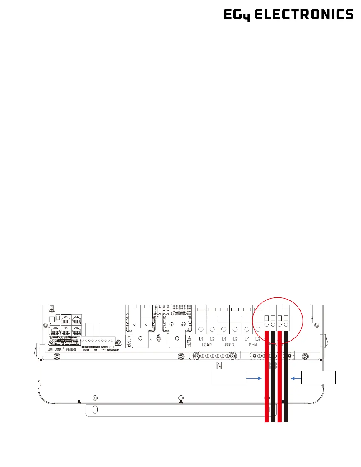
Please see the diagram below for PV terminal labeling.

 Loading...