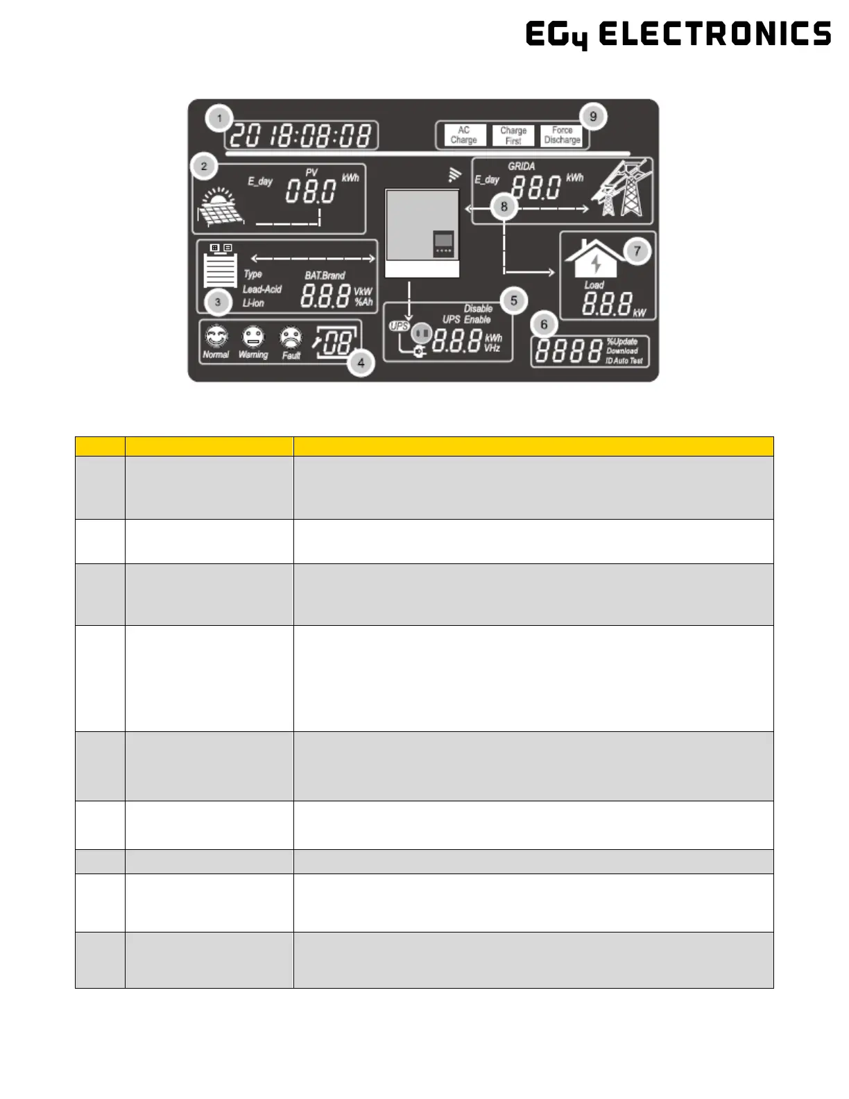
10.3.1 LCD DISPLAY
The data on the LCD screen updates every 3 seconds as various information is displayed in
each section. See table on next page for more details.
1
General Information
Display Area
Displays the current system status by default. Pressing the Up/Down buttons will
cycle through Time, Date, Single/Parallel Inverter Setting, Inverter Serial Number,
and Firmware Version. When entering new settings, the selection information is
displayed in this area.
2
Photo Voltaic (PV) Data
Cycles every 3 seconds through: PV1 Voltage, PV2 Voltage, PV1 power, PV2
Power, PV1 Energy (day), PV2 Energy (day), PV1 Energy (total to-date), and PV2
3
Battery information and
data
Displays the battery type and brand. For lead-acid batteries, this area will cycle
every 3 seconds through the CV voltage, Float Charge Voltage, Cut-off Voltage, and
Discharge End Voltage. For Lithium-ion batteries, this area will cycle every 3
seconds through the Voltage (V), SOC (%), Power (kW), and Capacity (Ah).
4
System Status and
Codes
There are three system status icons, Normal, Warning and Fault, and a 2-digit field
that displays codes.
• Status = ‘Normal’: nothing is displayed in the 2-digit field
• Status = ‘Warning’: warning code is displayed in the 2-digit field.
• Status = ‘Fault’: fault code is displayed in the 2-digit field.
• System in ‘Setting’ mode: current Setting is displayed in the 2-digit field.
5
UPS/EPS output
information and data
When the UPS function is enabled, this area will cycle every 3 seconds through
UPS1 V, UPS1 Hz, UPS1 kW, UPS2 V, and UPS2 kW. There is no UPS2 Hz,
because it will always be the same as UPS1 frequency by default.
UPS1=Phase1=L1, UPS2=Phase2=L2.
6
percentage of AC output
When in Off-Grid mode, this area will display the percentage of the maximum AC
output power. Relevant information is displayed during firmware updates
7 Load consumption
Displays the power consumption by the load in the On-grid Mode.
8
Grid and Generator
information
Cycles every 3 seconds through: Grid1 Voltage, Grid2 Voltage, Grid Hz, Gen1
Voltage, Gen2 Voltage, Gen Hz, Grid Power, Grid Energy (day), and Grid Energy
(total to-date). Grid1=Phase1=L1, Grid2=Phase2=L2; Gen1=Phase1=L1,
9 Working mode area
When the user makes changes to the 6000XP inverter through the LCD, this area
will display the AC Charge, Charge First and Force Discharge settings. Otherwise,
this area displays nothing.

 Loading...