8. Ensure all inverters are set to “P1” phase.
9. Ensure the battery to inverter communications cable is properly connected from master battery
to inverter.
Note: If commissioning a single inverter system, ensure setting 21 is set to NoPL (no parallel),
and then finish the commissioning.
Commissioning Steps:
1. Power on the system per the start-up sequence in section 12.
2. Turn on the battery and make sure the communication works on all units.
3. Check the parallel info via the Home page on the LCD.
4. Before connecting load to load output terminal, check the output of L1 to N, L2 to N and L1 to
L2. to ensure no voltage is present.
5. Add some small loads to the load output and verify power output.
6. Finish the commissioning.
Note: To determine proper host and slave definition of the inverters, provide power to each before
turning on. Turn on the EPS Output (AC Output) on the host inverter first, to designate it as host.
Power on each inverter paralleled past the host to define them as slaves. On the main inverter
display, press “down” three times, then check the numbers & letters in the top left. Host inverter
should read “1P-H:P1: 1”, and slave should read “1P-S:P1: 1”.
5. END USER SETTINGS
The EG4 Monitor Software can be used to configure the desired functionality of the 6000XP Inverter.
The following sections describe the different fields in the Monitor Software GUI and their definitions for
those with an end-user account.
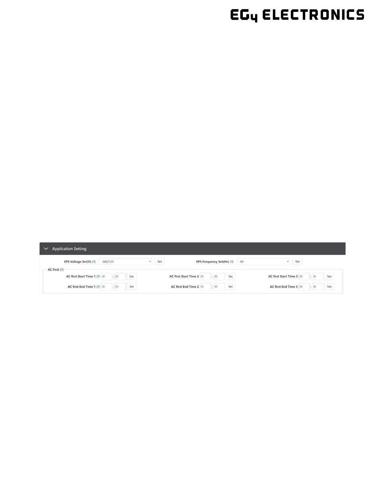
5.1 APPLICATION SETTING
• EPS Voltage Set(V): Set the voltage of the inverter’s output.
• EPS Frequency Set(Hz): Set the frequency of the inverter’s output.
AC First
• AC first Start Time 1, 2, 3: Set the start time for when inverter passes through from grid
to loads.
• AC first End Time 1, 2, 3: Set the end time for when inverter passes through from grid to
loads.

 Loading...