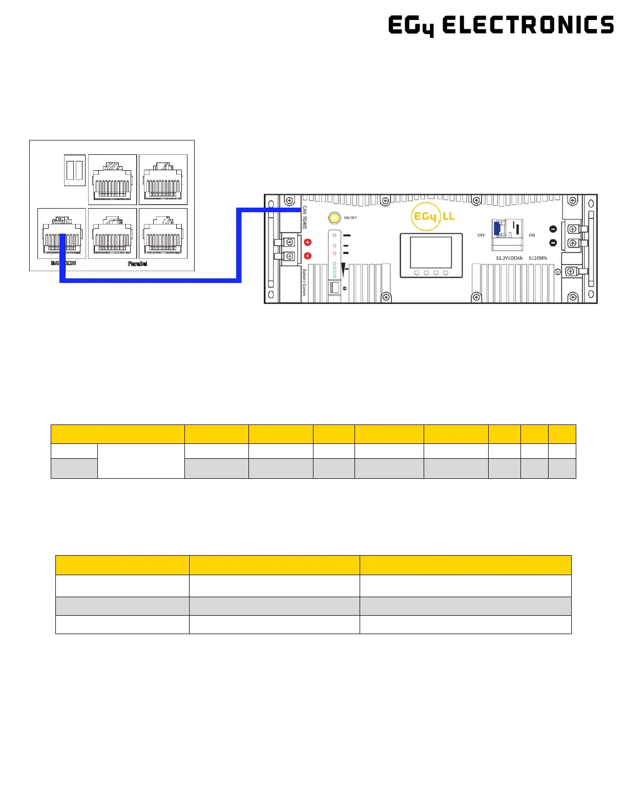
4.5.2 LITHIUM BATTERY COMMUNICATIONS
Upon successful installation of your batteries, follow the next steps to enable closed-loop
communications (with compatible battery modules) between batteries and inverter.
1. Connect either the CAN or RS485 (depending on make/model of battery) communications cable
between inverter and battery. See diagram below.
2. For the inverter to communicate with the battery BMS, you must change setting 3 to “Li-ion”.
The inverter will then switch to a secondary setting. Here, you select your make/model of battery
and press enter to register the change. For EG4 batteries, you would select “0” after confirming
“Li-ion” as the battery type.
Note: If needing to extend your inverter to battery communication cable or create your own, please
refer to the following table for the inverter pinout descriptions.
For battery specific pinouts, please refer to the respective battery user manual.
PIN # 1 2 3 4 5 6 7 8
Pin
Description
RS485
BMS_485 B BMS_485 A X X X GND
4.6 AC WIRING INFORMATION
When sizing AC wires, please adhere to the following information.
AC Cable Requirements:
Terminal Connection Wire Size Torque Values
GRID 8 AWG (10mm²) 2 Nm (18 in. lbs.)
8 AWG (10mm²) 2 Nm (18 in. lbs.)
8 AWG (10mm²) 2 Nm (18 in. lbs.)
Ground-Neutral Bonding
The information below describes the nature of the ground and neutral in the inverter and
their relationship to the system. Always consult with your installer or a licensed electrician to
ensure that the right configuration is being used:
• The neutral line is a solid connection between AC input and AC output (known as
a Common Neutral Architecture).
• The neutral line between the AC input and AC output is never disconnected.

 Loading...