AC output (LOAD) to power loads. The pass-through relay on the inverter Generator terminal (GEN) is
30A. When the generator is on, please ensure the total load and charge current does not exceed 30A.
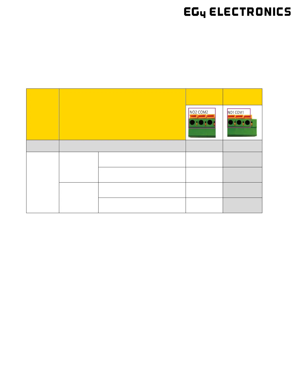
4.7.2 INTEGRATED DRY CONTACTS
This inverter has two dry contact connections that can be used to remotely enable external
devices such as a generator. The Dry Port (NO2, COM2) can be used to remotely enable an
external device when the battery voltage reaches a pre-set warning level. Similarly, the GEN
Port (NO1, COM1) can be used to remotely start a generator. To do so, the generator start
signal must be connected to the inverter GEN contacts, NO1 and COM1. The following table
shows the dry contact status under various system conditions.
4.7.3 GENERATOR AC CONNECTIONS
Please follow the steps listed below to ensure your Generator connections are installed correctly.
Note: If running more than one inverter in the system, you must wire the generator to provide power to
every inverter running in parallel for the inverters to function as intended.
Step 1: Before making any wiring connections, be sure to have the inverter(s) powered off, the
generator powered off, and all circuit breakers open (off) to prevent damage to the unit.
Step 2: Properly identify the generator’s output lines. By US wiring standards, L1 wire will be black, L2
will be red, Neutral will be white, and ground will be green. Once identified, remove ≈10mm from the
insulation sleeve on the wires.
Step 3: Ground the generator’s output ground to the Ground Bus (labelled PE) of the inverter.
Inverter
Status
Condition
Dry Port
Status
GEN Port
Status
Power Off Inverter is off and no output is powered Open Open
Power On
Without Grid
Battery Voltage/SOC < Generator
Charge Start Voltage/SOC
Closed Closed
Battery Voltage/SOC > Generator
Charge Stop Voltage/SOC
Open Open
With Grid
Battery Voltage/SOC < Generator
Charge Start Voltage/SOC
Closed Open
Battery Voltage/SOC > Generator
Charge Stop Voltage/SOC
Open Open
Note: NO = Normally Open, COM = Common
Dry Port and GEN relay maximum specification: 250VAC, 5A

 Loading...