Mortal danger from electric shock
Exposed power contacts - High Voltage
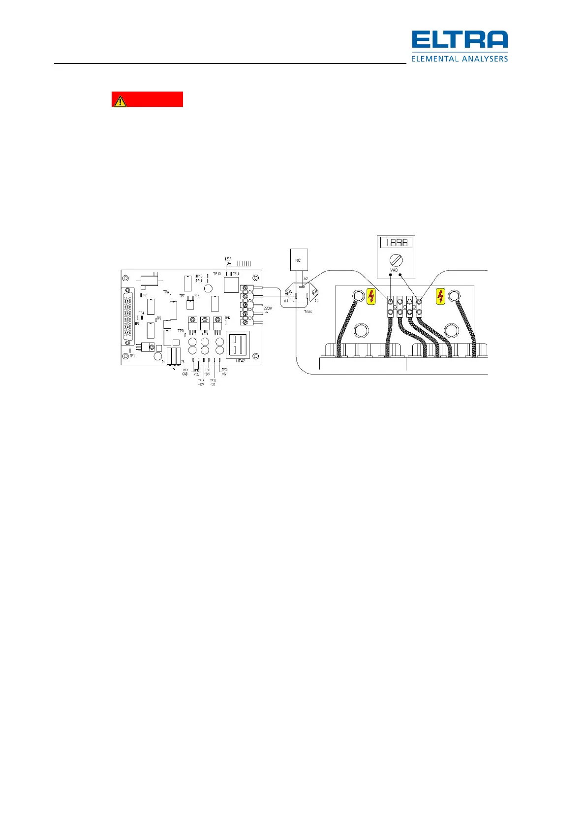
When checking for induction power, always keep the furnace closed!
On the primary side of the high voltage transformer, you should be able to measure about 210 V
AC; if not, the triac is possibly defective.
The filament voltage can be also measured as shown below. A direct measurement at the
tube’s socket rules out eventual interruptions on the way of the voltage from the transformer to
the socket.
: Measurements - high voltage transformer
Once there is voltage on the transformer the triac must be OK. A relatively low voltage on the
transformer could be a result of too high current so that the HF-42 board reduces the phase
angle. IF so there is most probably a faulty component in the oscillator circuit preventing it from
oscillating so that the oscillator tube takes a high DC current.
NOTICE
This can damage the tube. Therefore when you start for testing whether there is combustion
keep your finger on the STOP button. If the sample does not start burning about 3 seconds after
the generator starts, then immediately stop the analysis.
One thing that will give further evidence is the current taken by the analyzer from the mains
power.
If the current goes up to a level of about 10A, then a faulty component prevents oscillations so
that the tube takes all this power causing overheating of the tube within several seconds.
If the current does not increase, it means that the generator does not take power, for example
due to a broken grid resistor.
In case the transformer has 210 V AC on the primary coil and there is still no combustion, check
the windings of the transformer as follows:
– switch off the analyzer and disconnect the main power plug.
– Measure the resistance of the primary coil.
– It must be extremely low, about 0.8 Ohms between the
– screws labeled 0 and 270.
– Measure the resistance of the secondary coil between the two screws on the –
ceramic insulators where the wires of the rectifier are connected.
– The resistance is approximately 322 Ohms.