Pos: 5.1 /0025 Ü berschriften/ELTR A 1. Überschrif ten/1 Adjustm ents eltra @ 8 \mod_139688 2697255_9.d ocx @ 60262 @ 1 @ 1
4 Adjustments
Pos: 5.2 /0025 Ü berschriften/ELTR A 1.1 Übersc hriften/11 Gas fl ow controller adj ustment and j umper settings E LTRA @ 6\ mod_1368776 355883_9.doc x @ 41371 @ 2 @ 1
4.1 Gas flow controller-adjustment and jumper settings
Pos: 5.3 /0010 ELTRA/0015 ser vice_instructions /CS-2000_ser vice/10Adjustm ents_CS-2000/1 005 Modul G as flow contr oller adjustments and jumper settings @ 9\m od_142554232171 9_9.docx @ 7 4562 @ 344 @ 1
4.1.1 Flow controller for induction furnace operation
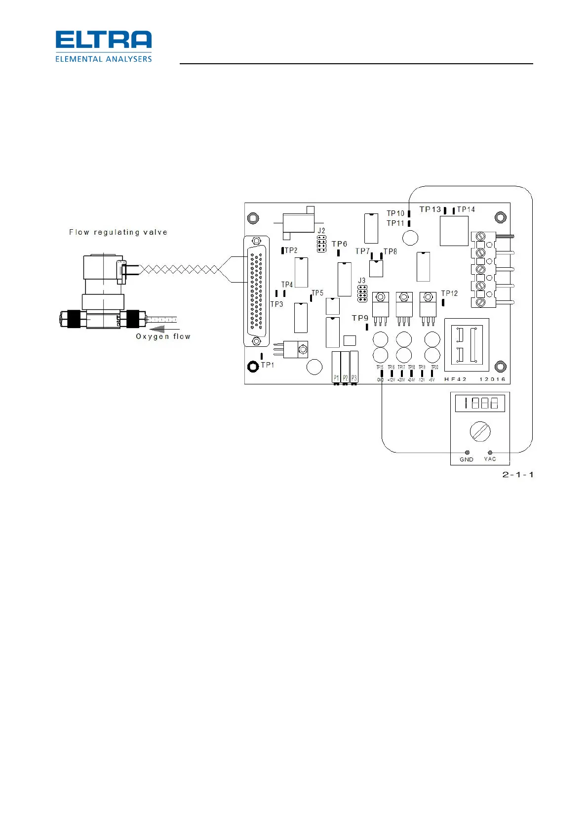
Gas flow controller adjustment
: Gas flow controller
– Set the flow rate with P1 of the HF 42, to about 180 l/h. Observe the flow rate on the
lower flow meter of the analyzer. Wait until the value is stable.
The output of the flow sensor is on TP10 of the HF 42 board; TP15 is GND. With a flow of
180 l/h, the voltage is about 2.5 - 3V.
NOTE: without flow, the output voltage of the sensor is not 0V but about 0.6V.
– Adjust with P3 until the voltage on TP7 is 5V.
On TP8, the activity of the pulse width modulator can be checked.
The output voltage to the gas flow regulation valve can be measured on TP3.
With a constant flow of about 180 l/h, it should be between 5 and 15 volts.
– Check and if necessary readjust the pressure regulator (PR3) in front of the flow
regulating valve.