Pos: 7.12 /0025 Üb erschriften/E LTRA 1.1 Übersc hriften/11 Fl ow sensor replac ement Eltra @ 8 \mod_1396 941567775_9.d ocx @ 60384 @ 2 @ 1
5.6 Flow sensor replacement
Pos: 7.13 /0010 E LTRA/0015 s ervice_instructio ns/CS-2000_s ervice/15 Ser vice_CS-2000/15 35 Modul Flow se nsor replace ment @ 9\ mod_1425543539 438_9.docx @ 74778 @ @ 1
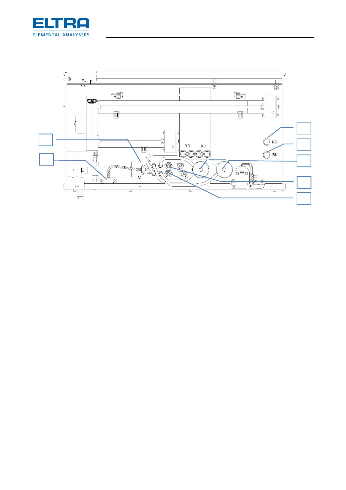
: Flow sensor(3-14)
– Set the power switch to pos. 0.
– Remove the left side panel of the analyzer’s cabinet.
– Remove the tubes (10) and (11) at the bottom-side of the infrared module.
– Remove the plastic tubes from the left hand side of the IR module.
– Remove the two plugs from the left hand side of the IR module.
– Remove the screw fixing the IR module in the analyzer. Take the infrared module out of
the analyzer.
– Remove the two tubes (5) and (6) from the flow sensor (9).
CAUTION They shouldn’t be interchanged when reassembling! In case of doubt see chapter
“IR-paths cleaning and replacing”
– Remove the two screws (7) underneath the flow sensor.
– Remove the old flow sensor (9) and install a new one.
– Reassemble the infrared rack in reverse order.
– Pay particular attention to the position of the tubes (5), (6), (10) and (11). In case of doubt
see chapter “IR-paths cleaning and replacing”
– Adjust the flow sensor. See chapter “Gas flow controller” where is written:
“Set the flow rate with P1 of the HF 42, to about 180 l/h. Observe the flow rate on the lower flow
meter of the analyzer. Wait until the value is stable.”