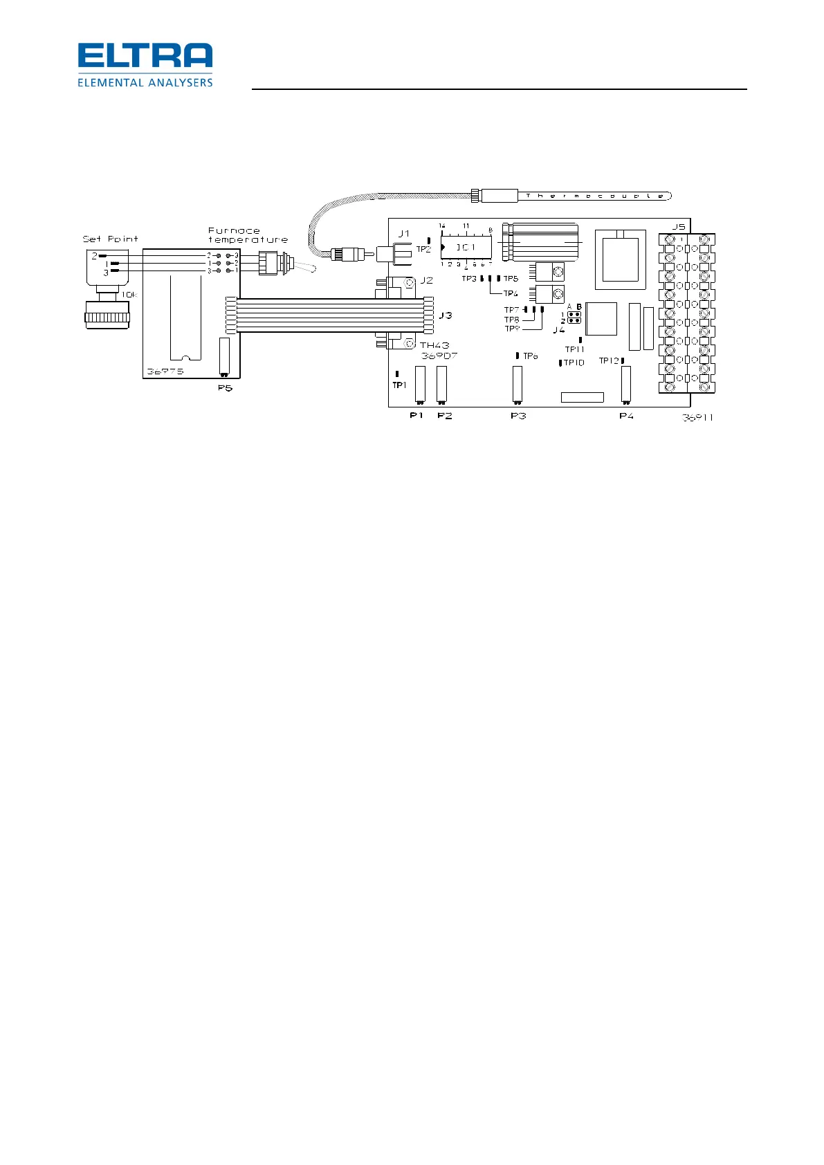
: Setting the furnace reulation card
1) Connect jumper J4 to A1 B1.
2) Disconnect plugs J2 and J3.
3) Turn trimmer P4 anticlockwise to the end-stop.
4) Set the power switch to pos. 2.
5) Measure about +15 V on pin 4 of the IC1; TP3 = GND.
6) Measure about +5 V on pin 14 of the IC 1.
7) Measure about –5 V on pin 11 of the IC 1.
8) Reconnect J2 and J3.
9) Turn the potentiometer on the front panel clockwise until maximum setting is reached.
10) Set the toggle switch to position set point .
11) Adjust with P1 to 1550 mV ( maximum ) on TP4 ( to be measured with a digital DVM ).
12) Set the trimmer to a value of 1550 on the LCD display.
13) Set the toggle switch to actual value ( furnace temperature ).
14) With P3 set the room temperature on the LCD display.
15) Set toggle switch back to set point.
16) Adjust set point to 1250°C.
17) Set toggle switch back to actual value.
18) Connect jumper J4 to A2 B2.
19) Adjust with P4 the max. AC current. For this purpose measure the current of the main
power with an external amperemeter. Adjust 20A.
CAUTION! Use a true RMS meter
20) Measure the voltage of the thermocouple on TP1, using an external multimeter with a
resolution of 0.01 mV.
21) By means of P2, set a value on the LCD display which relates to the value on the
multimeter; e.g. if the multimeter shows 11,30 mV, then the LCD display must show
1130°C. Once the furnace temperature is stable at the set temperature of 1250°C, the
multimeter must show 12.50 mV and the LCD display must show 1250°C. Repeat the
adjustments, in case the readings deviate.