– The flow sensor (1)
– The flow regulating valve (V6)
– The flow control board HF 42
The flow sensor measures the gas flow rate, and converts its flow rate into an electrical signal
(DC voltage).
The HF 42 board compares this flow value with the flow value set by P1.
The signal resulting from the comparator controls a pulse width modulator.
Its output can be seen on TP 8, TP 15 is GND.
The pulse width modulated signal controls a power transistor, which drives the flow regulating
valve.
The duty cycle of the output signal determines the average DC voltage on the valve. In normal
operation with a flow of about 180 l/h and with not depleted chemicals, the DC voltage across
the valve coil is around 10V. This voltage can be measured between TP3 and TP17. This
voltage on the valve has the value needed at any moment for keeping the flow constant, in
other words for keeping the sensor voltage equal to the value set with P1.
4.1.2 Flow controller for resistance furnace operation
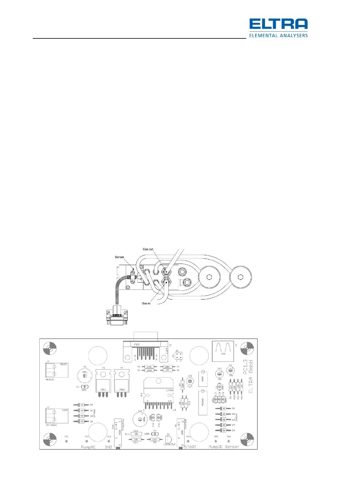
The flow sensor is common for both, induction and resistance furnace operation.
The sensor output is connected to both:
To the input of the HF42 board controlling the regulating valve V6 in induction operation and to
the input of the pump control board PC-1.3 controlling the pump in resistance furnace operation.
See chapter “Wiring diagrams” and “Gas flow diagram”.