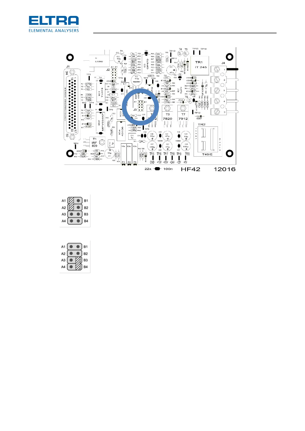
: Jumper position for continuous flow
In this case there is continuous flow when the main power switch is on Position 2.
Resistance furnace operation:
1. The flow sensor (same sensor also used in induction operation)
2. The electronic board PC-2 (see chapter “Gas flow controller and jumper settings”).
3. The gas pump (see chapter “Gas flow system”).
Pos: 3.6 /0025 Ü berschriften/ELTR A 1.1 Übersc hriften/11 No co mbustion @ 9\mod_14255 44797746_9.doc x @ 74944 @ 2 @ 1
3.3 No combustion
Pos: 3.7 /0010 ELTRA/0015 ser vice_instructions /CS-2000_ser vice/05Faults_C S-2000/05 15 Modul No com bustion @ 9\m od_14255393 52573_9.docx @ 74117 @ 33 333334444444 @ 1
3.3.1 Induction furnace operation
After clicking START of analysis or pressing F5 but the sample doesn’t burn, check the reports
in the “status window” on the pc screen.
The following describes how to proceed depending on the displayed message
No oxygen pressure
See Chapter “No or low oxygen pressure”