206
EMC Connectrix B Series v6.2 ED-DCX-4S-B Hardware Reference Manual
Port Side Exhaust Kit Installation Procedure
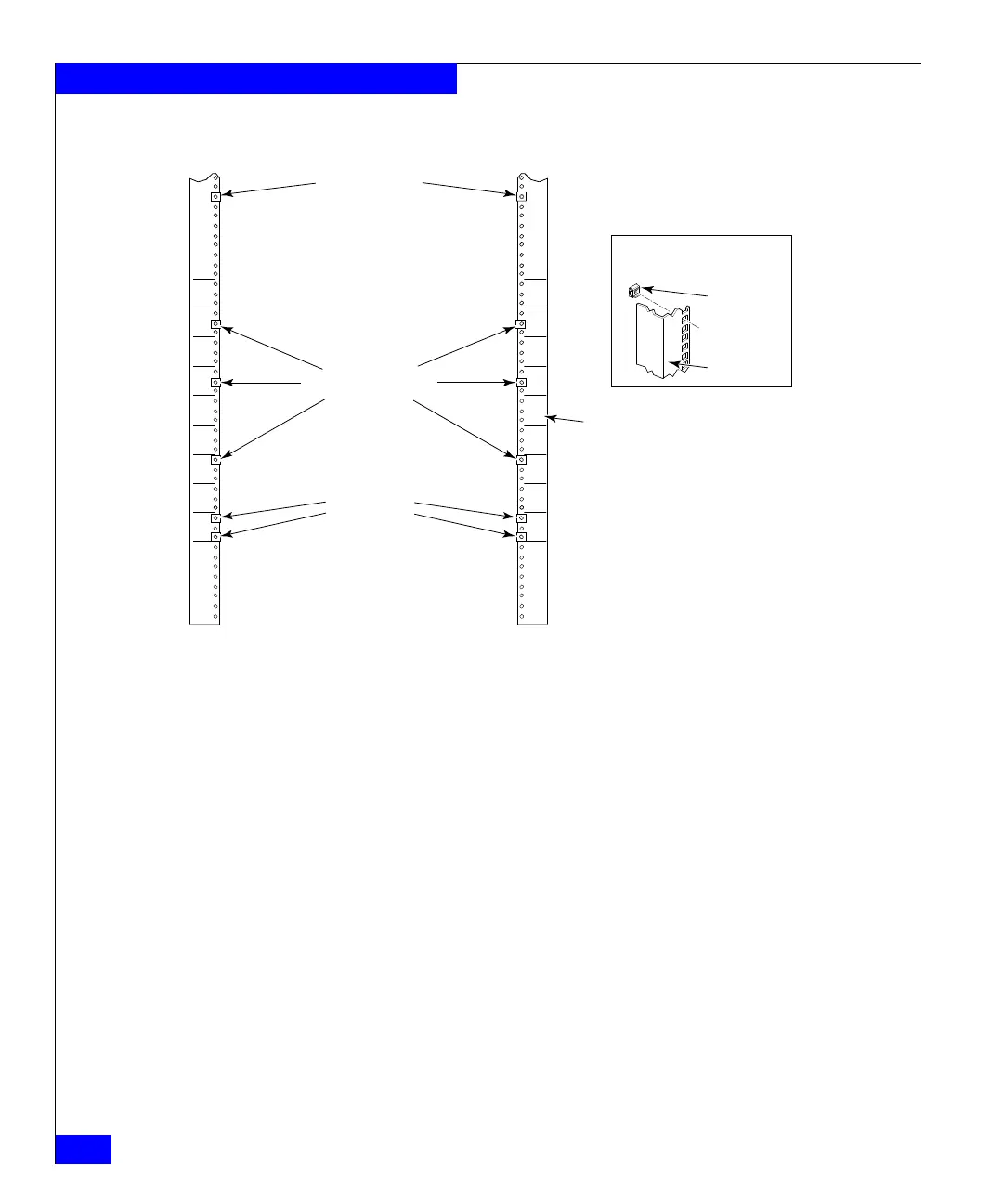
Figure 45 Clip and retainer nut locations on cabinet rails
3. Install the shelf saddle (E in Figure 44 on page 204) to the nonport
side of the equipment cabinet .Install the saddle in the same
vertical location as where the shelf installs on the port side of the
rack. In using Figure 45 on page 206 as example, if the shelf is
installed in location 23 on the port side, install the saddle in
location 23 on the nonport side. Ensure that the words “THIS
SIDE UP” on the saddle face towards the port side of the rack
(refer to Figure 46 on page 207).
Secure the saddle to the equipment cabinet using four 10-32
screws with washers (G in Figure 44 on page 204), two screws on
each side of the saddle. Tighten screws according to specifications
under “Torque requirements” on page 204.
Setup for Rails
with Square Holes
Note
Screws, clip nuts, and retainer nuts for
the ED-DCX-4S-B are provided in the
ED-DCX-4S-B hardware accessory kit.
Retainer Nut
(Item G)
Rail
31
30
29
28
27
26
25
24
23
Rail
Attaching Clip Nuts
for Round-Hole Rails
31
30
29
28
27
26
25
24
23
Clip or Retainer
Nut Locations
for ED-DCX-4S-B
Clip or Retainer
Nut Locations
for Shelf
 Loading...