ControlWave Instruction Manual (CI-ControlWave)
Revised Nov-2010 Introduction 1-5
Note: For detailed technical specifications, please see document
CWPAC available on our website
http://www.emersonprocess.com/remote.
1.4 CPU Module
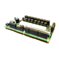
The CPU (central processing unit) module houses the multi-layer PCB,
which contains the ControlWave CPU, I/O monitor/control, memory,
and communication functions. It also may include the optional
Secondary Communications Board (SCB).
The CPU module includes:
AMD Elan SC520 microprocessor running at 100 MHz
two RS-232 communication ports
one 10/100baseT Ethernet port
2 MB of battery backed Static RAM (SRAM)
64 MB of Synchronous Dynamic RAM (SDRAM)
512 KB boot/downloader FLASH
32 MB simultaneous read/write FLASH memory
transmit (TX) and receive (RX) LEDs for each communication port
Keyed run/remote/local operation switch
configuration DIP switches (described in Chapter 2)
Port 80 display to show status codes
You can order the CPU module with the optional secondary
communication board (SCB) for additional communication ports. See
CPU Module Configurations.
CPU Module
Configurations
The CPU module has several basic configurations, all of which have an
on-board backup battery and different combinations of
communications ports.
Table 1-1. CPU Module Configurations
Number of
RS-232
Ports
Number of
RS-485
Ports
Number of
Ethernet Ports
Notes
2 0 1 No SCB.
3 1 2 For this port count, 1 RS-232, 1 RS-485,
and 1 Ethernet port reside on the SCB.
3 1 1 For this port count, 1 RS-232 and 1 RS-
485 port reside on the SCB.
2 2 1 For this port count, both RS-485 ports
reside on the SCB.
 Loading...

