ControlWave Instruction Manual (CI-ControlWave)
3-20 I/O Modules Revised Nov-2010
Table 3-7 Analog Input Module Configurations
Part Number Number of AIs Termination
Connector
Notes
396352-01-4 16 Local
4-20 mA
396352-03-0 8 Local
4-20 mA
396352-11-1 16 Remote
4-20 mA
396352-13-8 8 Remote
4-20 mA
396352-14-6 8 Remote 1-5 Vdc
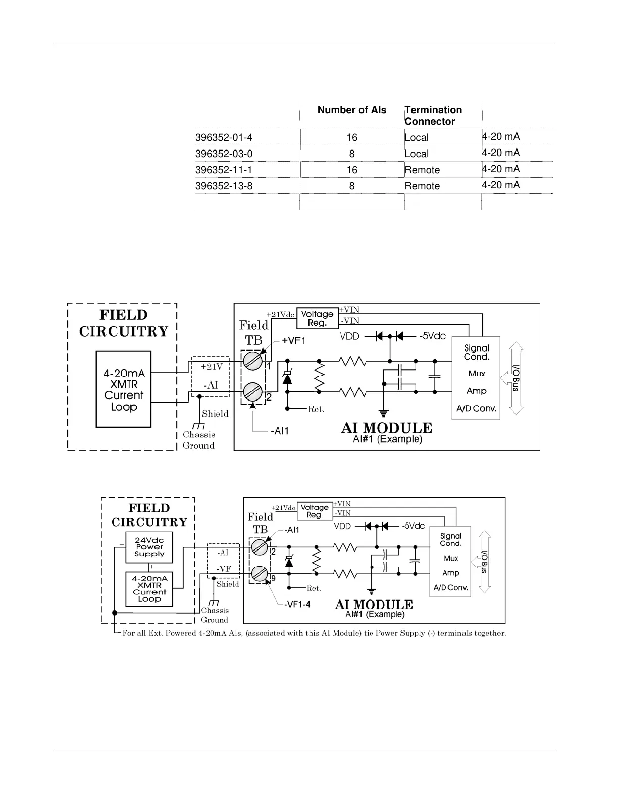
Wiring the Module
Figure 3-18 shows terminal assignments for a locally terminated AI
module; Figure 3-19 and Figure 3-20 show terminal assignments for a
4-20m
A and a 1-5Vdc remotely terminated AI, respectively.
Figure 3-15. Internally Sourced 4-20mA Current Loop AI - Wiring
Diagram
Figure 3-16. Externally Powered 4-20mA Current Loop AI - Wiring Diagram