ControlWave Instruction Manual (CI-ControlWave)
Terminal Block
Connector TB1
You must power the watchdog connector (TB1) from an external power
supply. Unplug removable connector TB1 from the PSSM and wire
power to the connector. We recommend you do not plug the connector
back into the PSSM until the CPU module is already installed in the
housing.
TB1 provides the following connections:
TB1-1 = VO - Watchdog MOSFET Switch Output
TB1-2 = VI - Watchdog MOSFET Switch Input
TB1-3 = VR = Redundant Unit Control Input
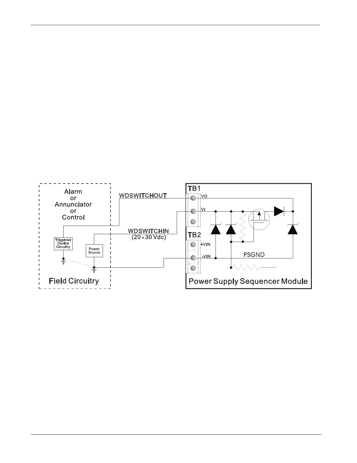
The VI input on TB2 (TB1-2) powers the watchdog switch; its switched
output connects to the VO output on the same terminal block (TB1-1).
You must reference the external power source connected to the VI
terminal to the return point of the input source powering the PSSM
[which is either –VIN or PSGND (TB2-3)]. See Figure 2-6.
TB1-1
TB1-2
TB2-1
TB2-3
TB2-5
Figure 2-6. Watchdog MOSFET Switch Wiring
2-16 Installation Revised Nov-2010