ControlWave Instruction Manual (CI-ControlWave)
UDI Bd.
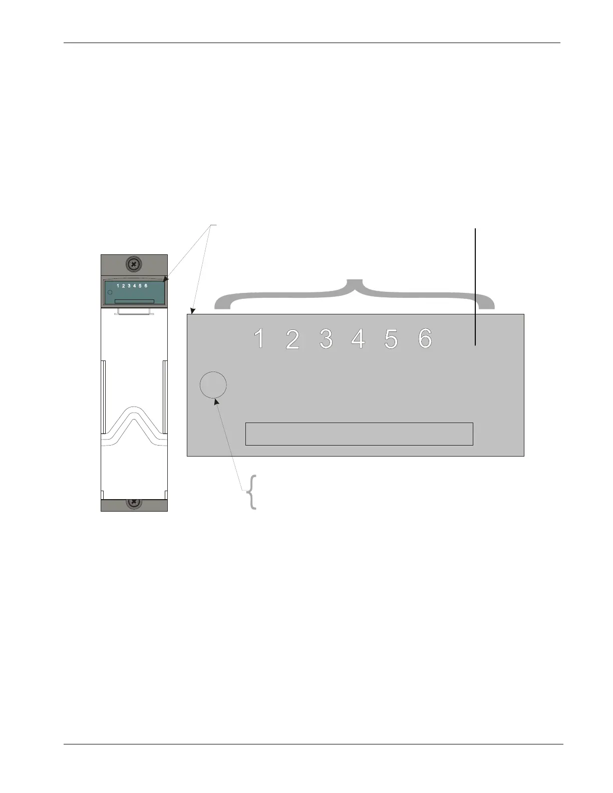
tatus LED
Red
=
UDI Bd. not recognized or failed.
. Status LED (Green) =
UDI Bd. recognized and normal.
.
OFF UDIXX = Input is not present.
UDI LED Board
LED Assignments
for UDI1 - UDI6
UDI Bd
ON UDIXX = Input is present
FAIL (Red) UDI Bd. Status LED
PASS (Green) UDI Bd. Status LED
UNIVERSAL DIGITAL INPUT
Note: The Status LED will turn ON (Red)
whenever power is initially applied to
the UDI Module. It will remain Red until
the CPU has recognized the UDI Module
and then it will turn Green and should
remain ON.
Revised Nov-2010 Service & Troubleshooting 5-19
UNIVERSAL DIGITAL INPUT
Figure 5-16. Universal Digital Input (UDI) Module LED Designations