ControlWave Instruction Manual (CI-ControlWave)
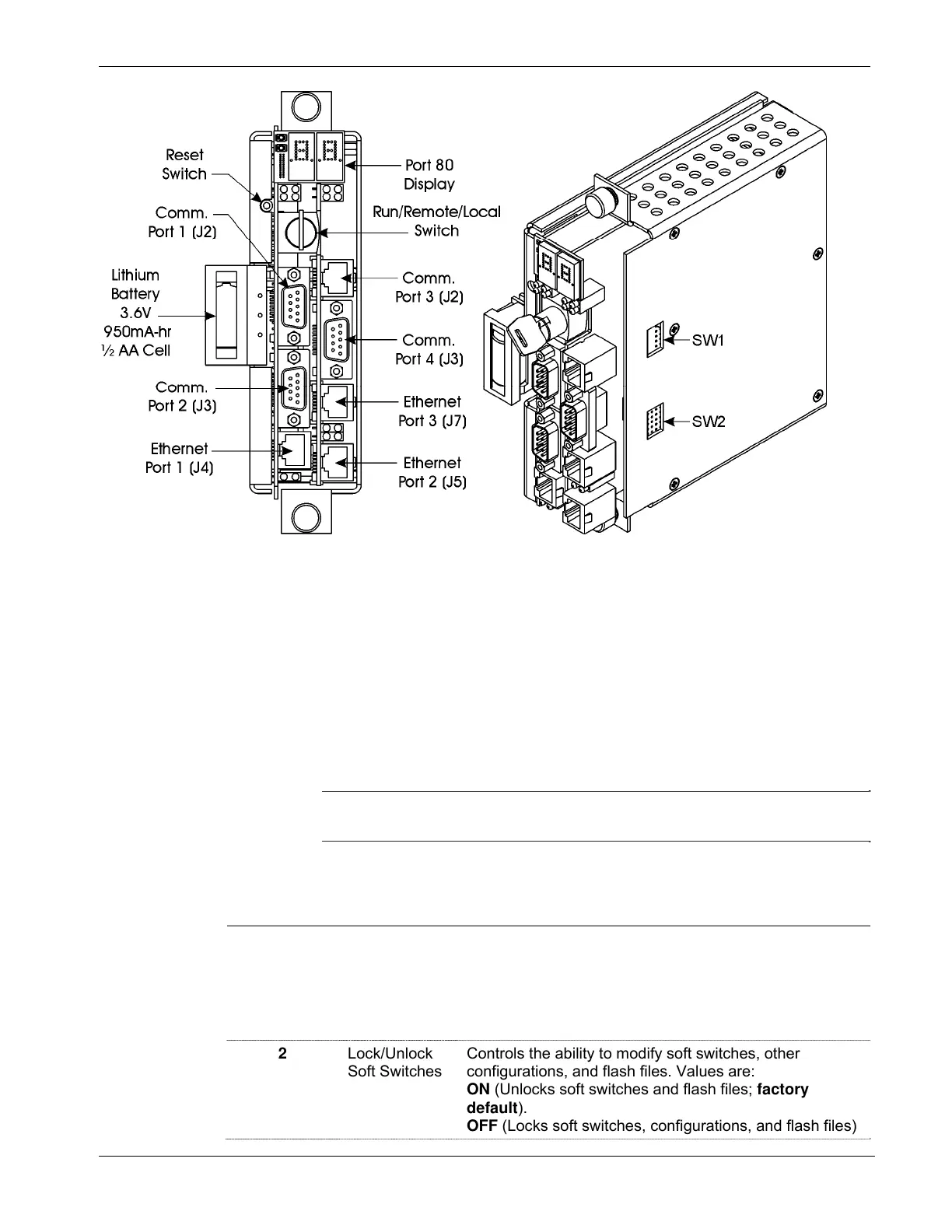
Figure 2-9. ControlWave CPU Module (with SCB)
2.4.1 Setting DIP Switches on the CPU Module
Before you install the CPU module, you must determine the settings for
its DIP switches. Refer to Figure 2-8 for the location of the DIP switch
banks on the CPU board itself. If you have a secondary
communications board (SCB) you must also refer to Figure 2-9 for the
location of the DIP switch banks on the SCB. Refer to Tables 2-2
through 2-4 for DIP switch setting values.
Note: Examine each bank of DIP switches carefully to note the switch
direction for ON or OFF.
Table 2-2. CPU Module Switch SW1
SW1 Setting Function Mode
1
Watchdog
Enable
Controls whether the system enters a watchdog state
when a crash or system hangup occurs and automatically
restarts. Values are:
ON (Enables watchdog circuit; factory default)
OFF (Disables watchdog circuit and prevents automatic
restart)
2
Lock/Unlock
Soft Switches
Controls the ability to modify soft switches, other
configurations, and flash files. Values are:
ON (Unlocks soft switches and flash files; factory
default).
OFF (Locks soft switches, configurations, and flash files)
Revised Nov-2010 Installation 2-19