ControlWave Instruction Manual (CI-ControlWave)
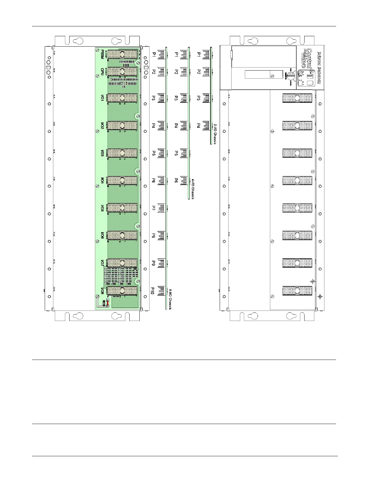
Figure 3-2. ControlWave Chassis Slot Assignments (with/without bezel
shown)
3.2 Status LEDs
Most of the I/O modules include one or more light emitting diodes
(LEDs) to provide diagnostic or status indications.
See Chapter 5 for information on the different LEDs.
3.3 Wiring
With a few exceptions (noted in the module descriptions), I/O modules
support either “local termination” (field wiring connected directly to the
3-4 I/O Modules Revised Nov-2010