ControlWave Instruction Manual (CI-ControlWave)
Battery backup for the real-time clock and the system’s static RAM
(SRAM)
Class I, Division 2 Hazardous Location approvals
1.1 Scope of the Manual
This manual contains the following chapters:
Chapter 1
Introduction
Provides an overview of the hardware and
general specifications for the ControlWave.
Chapter 2
Installation
Provides information on the housings, the
Power Supply/Sequencer module (PSSM), and
the CPU module.
Chapter 3
I/O Modules
Provides general information and wiring
diagrams for the I/O modules.
Chapter 4
Operation
Provides information on day-to-day operation of
the ControlWave.
Chapter 5 Service and
Troubleshooting
Provides information on service and
troubleshooting procedures.
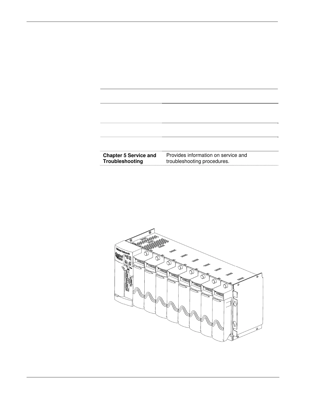
1.2 Physical Description
Each ControlWave has a printed circuit board (PCB) backplane
mounted in a stainless steel housing, a Power Supply/Sequencer Module
(PSSM), a CPU module which may include an optional Secondary
Communication Board (SCB) and—depending on the backplane and
housing size—up to eight I/O modules.
Figure 1-1. ControlWave with 8 I/O Modules
1-2 Introduction Revised Nov-2010