ControlWave Instruction Manual (CI-ControlWave)
3-40 I/O Modules Revised Nov-2010
Wiring the Module
Figure 3-34 shows field wiring for locally terminated isolated LLAI
modules. Figure 3-35 shows field wiring for remotely terminated
isolated LLAI modules.
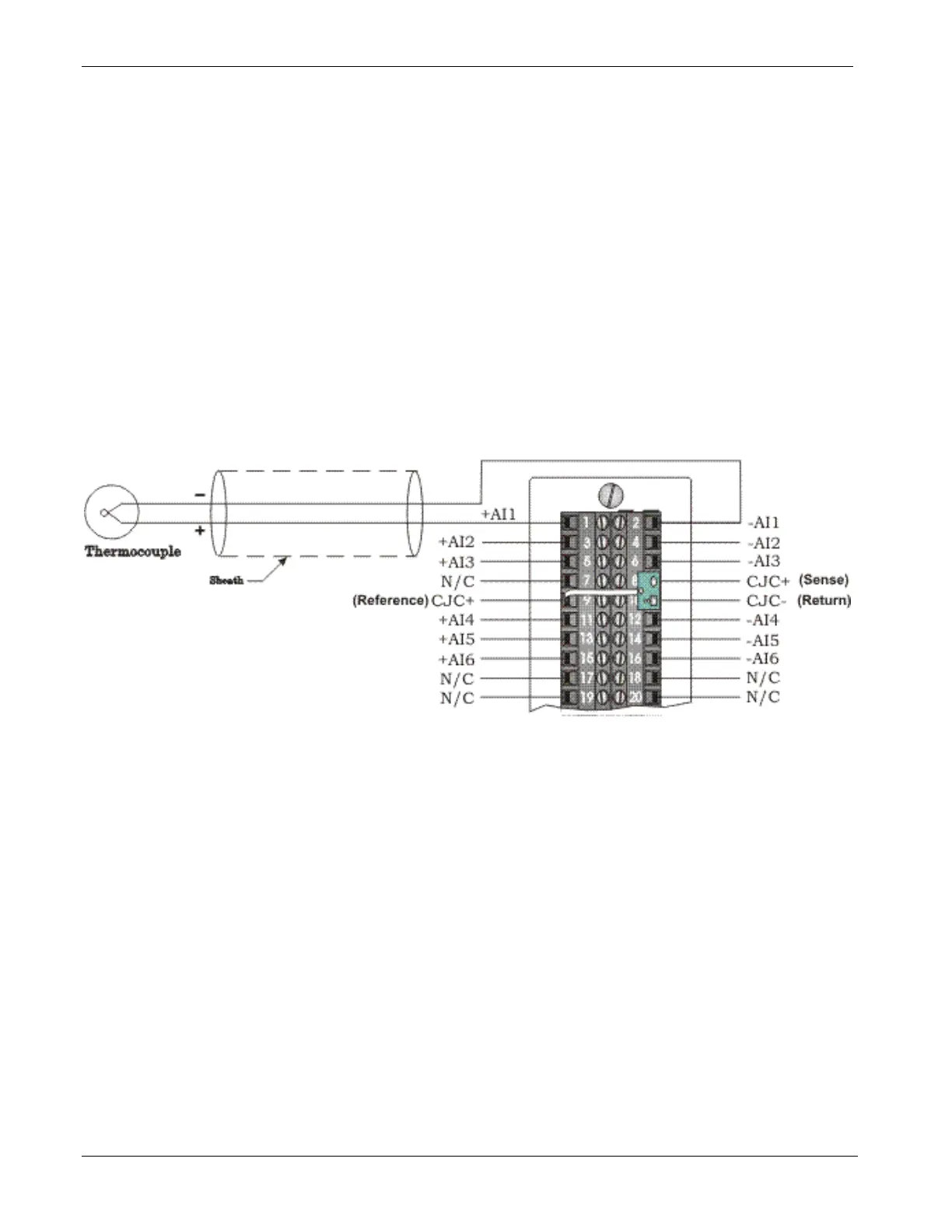
The cold junction compensation (CJC) with a built-in RTD provides
thermocouple temperature compensation at the terminal block and is
electrically isolated. Pins 8, 9 and 10 of the local terminal block source
and sink the CJC’s RTD.
Figure 3-35 also provides diagrams showing the wiring for
thermocouples and the 3-wire RTDs to a locally terminated LLAI
module. Wiring assignments (that is, +AI#, -AI#, +CJC (Sense), -CJC
(Return) & +CJC (Reference) are similar to those assigned to the remote
DIN-rail mountable terminal blocks. A small CJC PCB is factory-
installed to the terminal block.
Figure 3-33, Isolated LLAI Module - Thermocouple Wiring Diagram