ControlWave Instruction Manual (CI-ControlWave)
Table 3-11. UDI Module Configurations
Part Number Number of UDIs Termination Connector
396362-02-8
6 local
396362-12-5
6 remote
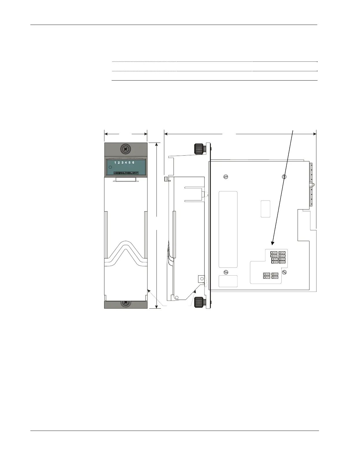
Setting Jumpers
Each input has a jumper to enable/disable debounce. Enabling debounce
activates filters that reduce spurious pulses caused by relay contact bounce.
Figure 3-24 shows the location of jumpers on the module.
Front Right Side
Terminal
Housing Ass’y.
1.820“
6.457“
6.970“
1
1
W1
W2
W3
W4
W5
W6
W7
W9
W10
W11
W12
W8
1
11
1
1
Jumper
locations
Figure 3-24. - UDI Module -Right Side View -Jumper Locations
3-30 I/O Modules Revised Nov-2010