ControlWave Instruction Manual (CI-ControlWave)
Table 3-12. Jumper Assignments: UDI Module
Jumper Purpose Description
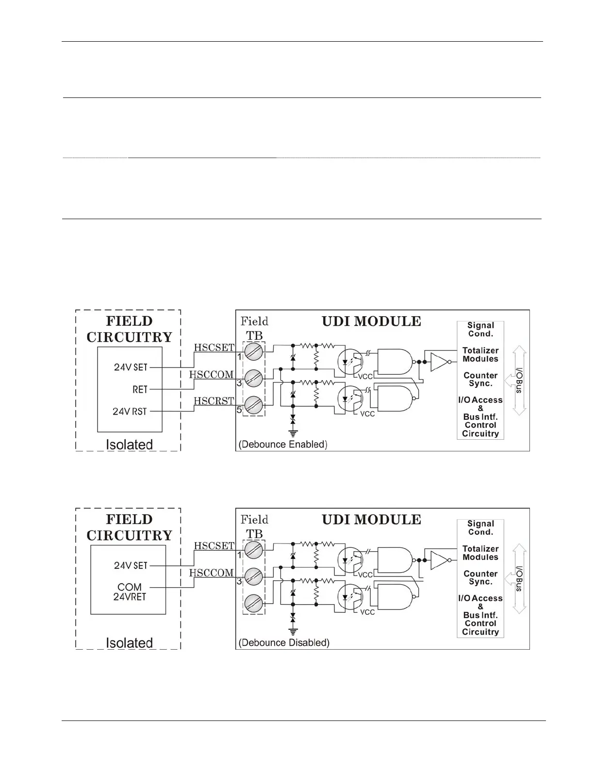
W1 Configures UDI1
Pins 1-2 installed = Enable Debounce (Factory default). A
change of state on both the SET and RST (reset) field
inputs is required to accumulate counts.
Pins 2-3 installed = Disable Debounce. A change of state
on the SET field input is required to accumulate counts.
W2 through
W6
Configures UDI 2 through UDI6
Pins 1-2 installed = Enable Debounce (Factory default). A
change of state on both the SET and RST (reset) field
inputs is required to accumulate counts.
Pins 2-3 installed = Disable Debounce. A change of state
on the SET field input is required to accumulate counts.
Wiring the Module
Figure 3-27 shows field wiring assignments for the locally terminated
UDI module. It also includes examples for relay contact and open
collector applications. Figure 3-28 shows field wiring assignments for
the remotely terminated UDI module.
Figure 3-25. UDI (Debounce Enabled) Wiring Diagram
Figure 3-26. UDI (Debounce Disabled) Wiring Diagram
Revised Nov-2010 I/O Modules 3-31