ControlWave Instruction Manual (CI-ControlWave)
5-28 Service & Troubleshooting Revised Nov-2010
4. After performing all diagnostic testing, exit WINDIAG and then
exit the NetView if you don’t have any other ControlWave units
to test.
When you close NetView, the system asks whether you want to
close OpenBSI. Select Yes.
5. Set switch SW1-8 on the CPU module to ON (open). The
ControlWave should resume normal operation.
5.4.1 Available Diagnostics
Using WINDIAG, you can test all ControlWave modules with the
exception of the PSSM. WINDIAG’s Main Diagnostics Menu (see
Figure 5-20) provides the following diagnostic selections:
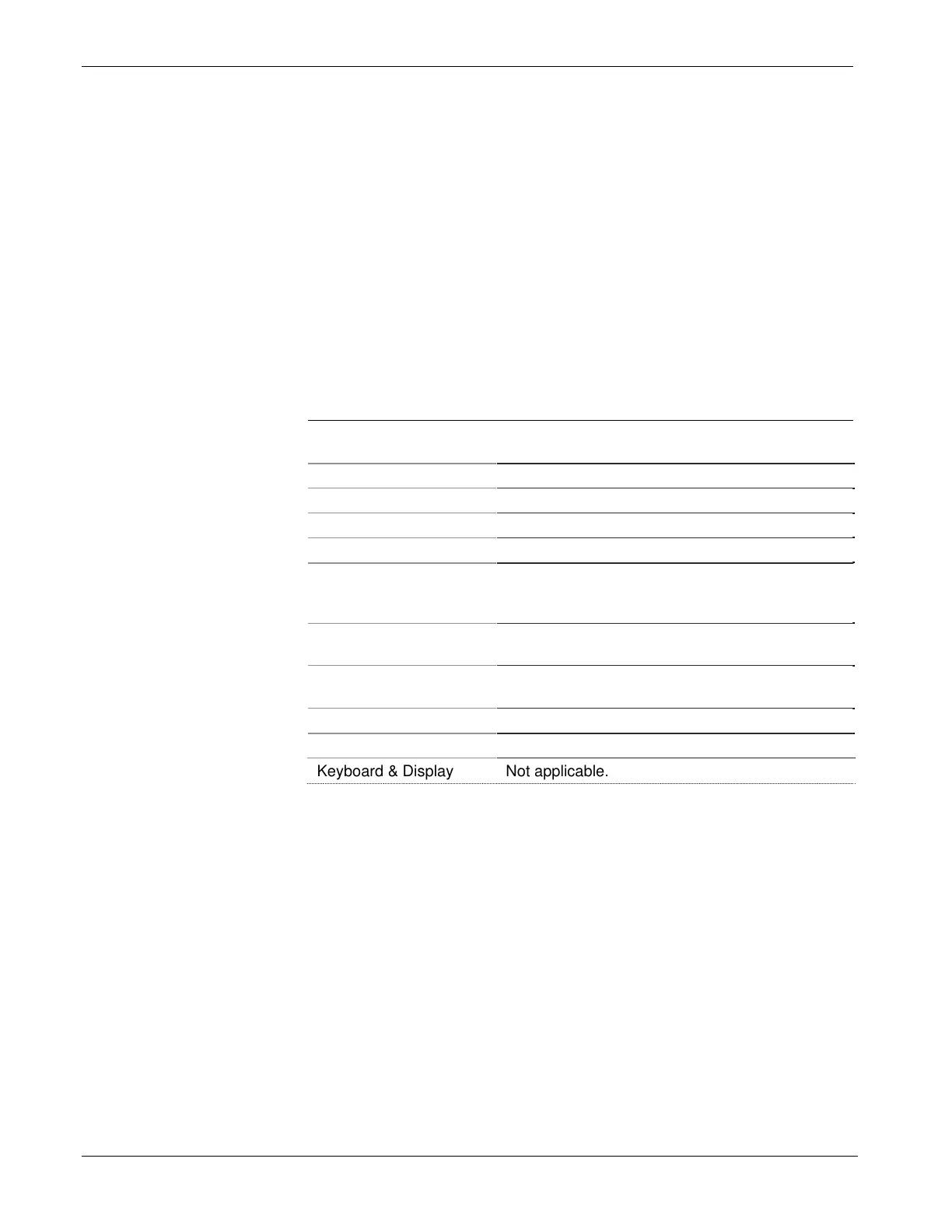
Option Tests
CPU & Peripherals Checks the CPU module (except for RAM &
PROM).
Analog Output Checks AOs on the Analog Output module.
High Speed Counter Checks the Universal Digital Input (UDI) module.
Prom/Ram Checks the CPU’s RAM and PROM hardware.
Analog Input Checks AIs on the Analog Input module.
Communications Checks Communication ports 1 through 4. The
loop-back tests require the use of a loop-back
plug.
Discrete I/O Checks DIs on Digital Input Module, DOs on
Digital Output Modules.
Ethernet Checks Ethernet Ports 1, 2, or 3. The loop-back
tests require the use of a loop-back plug.
Low Level AI Checks LLAI modules and RTD modules.
EEPROM Checks the EEPROM.
Keyboard & Display Not applicable.
Port Loop-back
Test
WINDIAG allows you to select the communication port (1 through 4)
to test. Depending on the type of network (RS-232 or RS-485) and the
port in question, a special loop-back plug is required:
Ports 1 and 2 (RS-232) use a 9-pin female D-type loop-back plug
(shown in the right side of Figure 5-21).