Redundant Power Supply Sequencer Module (RPSSM)
LED Indicators on the RPSSM
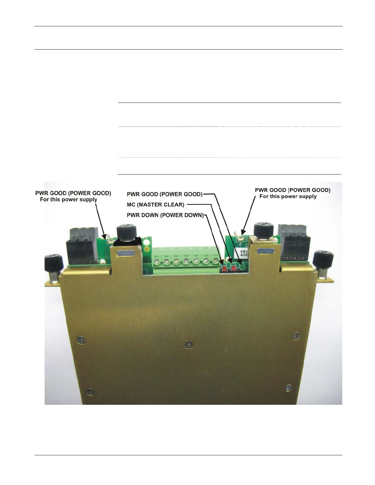
Three light emitting diodes (LEDs) are visible through the front cover of
the RPSSM (see Figure P-10). Table P-3 describes their functions.
Table P-3. LED Descriptions
LED label
Color
(when lit)
Meaning
PWR GOOD Green
Lights when power is within correct range,
and remains on as long as power to unit
remains within normal operating ranges.
MC (Master Clear) Red
Lights when the CPU is not running, and
I/O has been reset to 0. This lights
momentarily when the unit first powers on
or when the unit resets.
PWR DOWN Red
Lights when power has fallen below
acceptable levels.
Figure P-10. LED Locations
Each power supply on the RPSSM also has an LED which lights when
power is good. If this LED does not light, remove the power supply and
check the fuse. Then ensure that the board is fully inserted.
Revised Nov-2010 Installation and Use P-9