ControlWave Instruction Manual (CI-ControlWave)
Revised Nov-2010 I/O Modules 3-9
for use in dry contact applications contain a +21 Vdc isolated power
supply powered through an output of the hot swap circuitry which
receives power originating on the backplane.
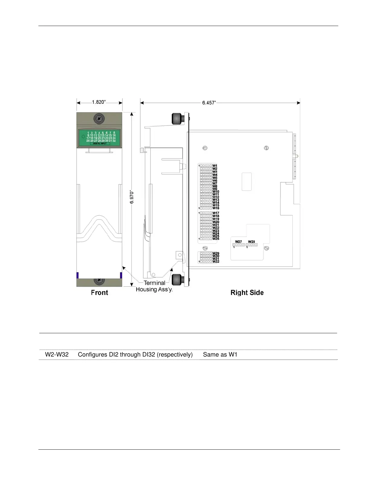
Setting Jumpers
You must set configuration jumpers for each DI. according to Table 3-
3. For a 16DI module, use W1 through W16, for a 32DI module, use
W1 through W32.
Figure 3-5. DI Module -Right Side View - Jumper Locations
Table 3-3. Jumper Assignments: DI Module
Jumper Purpose Description
WI Configures DI1 Pins 2-3 & 4-5 installed = External Power DI
Pins 1-2 & 3-4 installed = Internal Source DI
W2-W32 Configures DI2 through DI32 (respectively) Same as W1
Wiring the Module
Figure 3-6 shows field wiring assignments associated with locally
term
inated DI modules; Figure 3-9 shows field wiring assignments
associated with remotely terminated DI modules. Figure 3-10 shows
an optional rem
ote termination module with built-in discrete relay
module that supports input from 120 Vac DIs. The special remote
termination module (with built-in discrete relay module) interfaces
with an externally sourced DI module.