Installation
Emerson
®
MPH2
™
User Manual 13
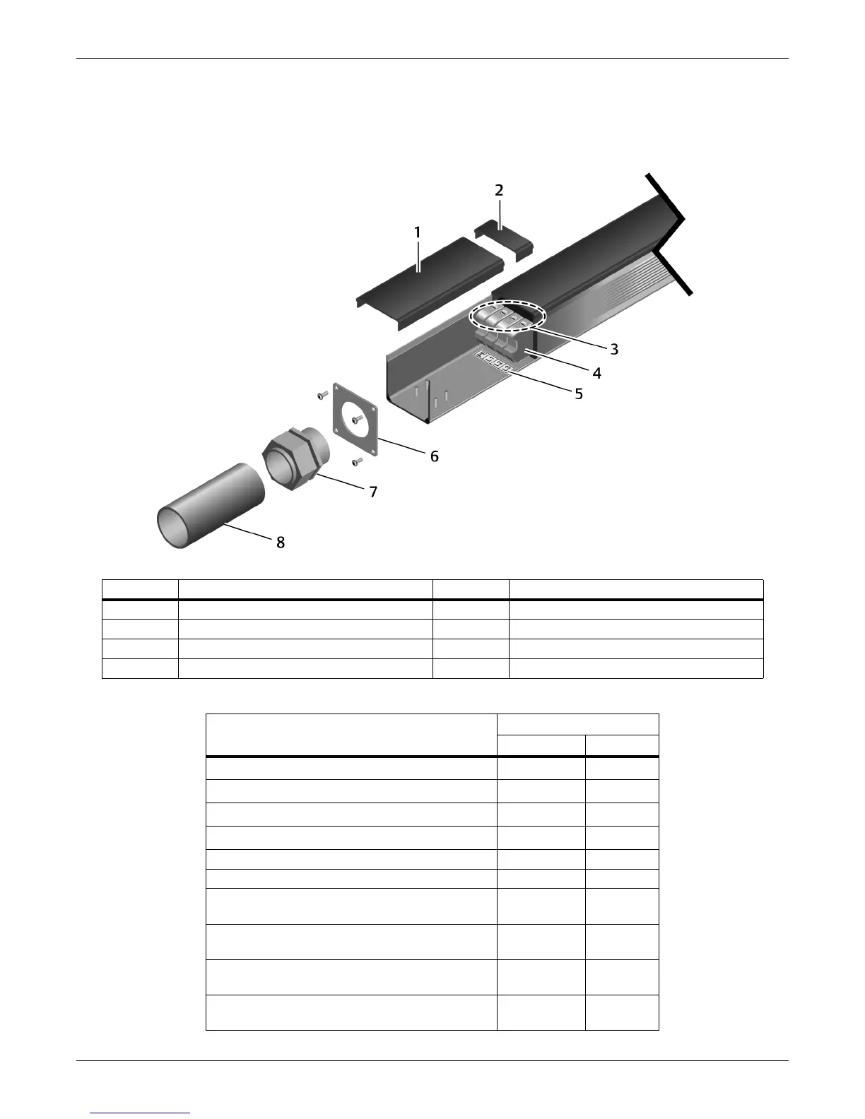
11. Slide the conduit into the conduit connector.
12. Tighten the conduit connector until it grips the conduit and crimps it securely.
Figure 2-2 Re-assembly to install an input power cable in conduit
Number Description Number Description
1 Cover plate 5 Strain-relief collar w/Phillips-head screws
2 Terminal-block screws 6 Metal end plate (attached with 4 screws)
3 Terminal blocks 7 Conduit connector (field-supplied)
4 Terminal-block labels 8 Conduit (cable not shown)
Table 2-1 Hard-wired models—Connection terminal ratings
MPH2 Rating
≤32 A >32 A
Conductor Cross-Section Solid, Minimum
0.2 mm
²
0.5 mm
²
Conductor Cross-Section Solid, Maximum
6mm
²
16 mm
²
Conductor Cross-Section Stranded, Minimum
0.2 mm
²
0.5mm
²
Conductor Cross-Section Stranded, Maximum 4 mm²
10 mm
²
Conductor Cross-Section, AWG/kcmil, Minimum 24 20
Conductor Cross-Section, AWG/kcmil, Maximum 10 6
Conductor Cross-Section Stranded, with Ferrule
without Plastic Sleeve, Minimum
0.25 mm
²
0.5 mm
²
Conductor Cross-Section Stranded, with Ferrule
without Plastic Sleeve, Maximum
4mm
²
10 mm
²
Conductor Cross-Section Stranded, with Ferrule
with Plastic Sleeve, Minimum
0.25 mm
²
0.5 mm
²
Conductor Cross-Section Stranded, with Ferrule
with Plastic Sleeve, Maximum
4mm
²
10 mm
²