please refer to the Mercury+ XU1 SoC Module Known Issues and Changes document [7] and to the Mercury+
XU1 SoC Module User Schematics [6].
21 22 23 24
PS Signal PS Signal PL Signal PL Signal Remarks
Name Location Name Location
PS_LED0#
21
J16 (MIO24) - - User function/active-low
PS_LED1#
21
G16 (MIO25) -
22
-
22
User function/active-low
- - LED2#_PWR_SYNC
23
AE8
24
User function/active-low
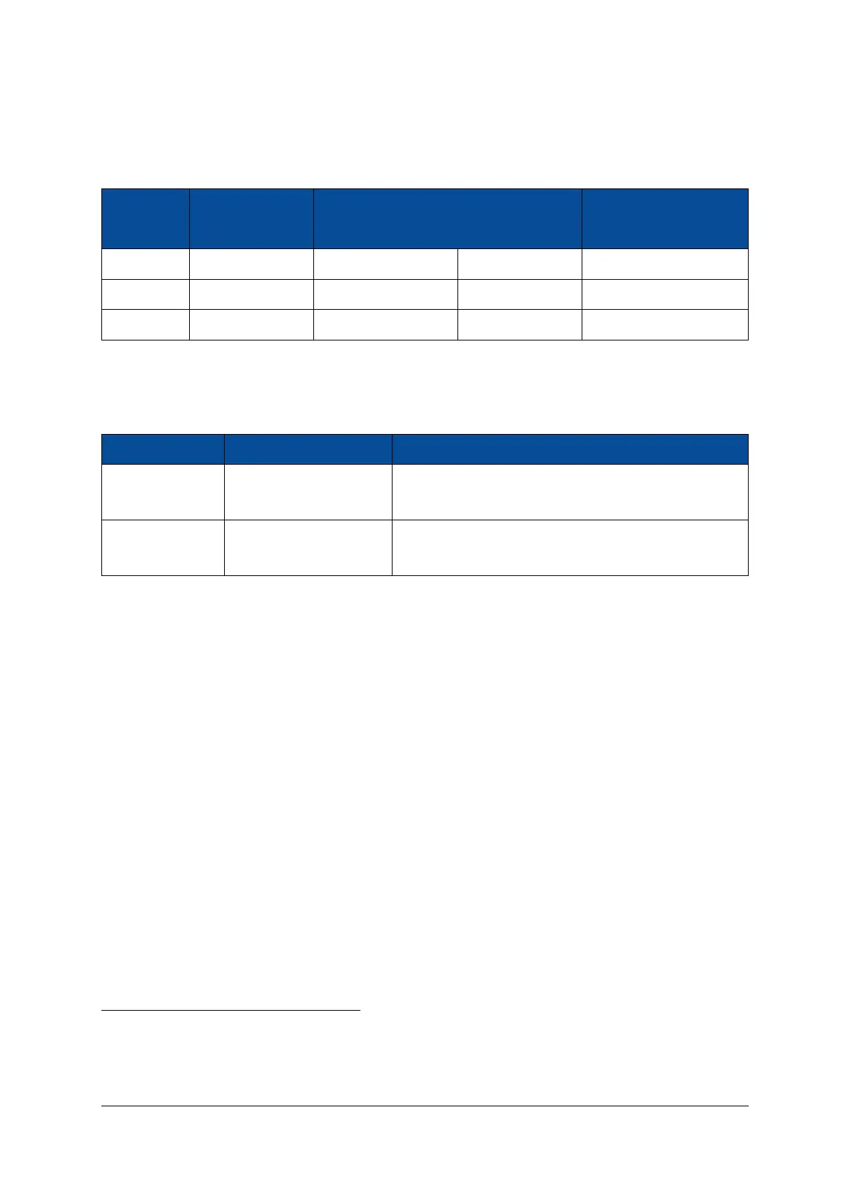
Table 23: User LEDs
In addition to the user LEDs, two status LEDs are equipped on the module, offering details on the configu-
ration process for debugging purposes.
PS Signal Name PS Signal Location Remarks
PS_ERROR P21 (PS_ERROR_OUT) Refer to Zynq UltraScale+ MPSoC Technical Reference
Manual [19]
PS_STATUS P22 (PS_ERROR_STATUS) Refer to Zynq UltraScale+ MPSoC Technical Reference
Manual [19]
Table 24: Status LEDs
On revision 1 modules, the PS_STATUS LED is active-low. Starting with revision 2, the polarity for the PS_STA-
TUS LED has been inverted, as the PS_ERROR_STATUS signal is active-high in the MPSoC device.
2.15 DDR4 SDRAM
There is a single DDR4 SDRAM channel on the Mercury+ XU1 SoC module attached directly to the PS side
and is available only as a shared resource to the PL side.
The DDR4 SDRAM is connected to PS I/O bank 504. The memory configuration on the Mercury+ XU1 SoC
module supports ECC error detection and correction; the correction code type used is single bit error cor-
rection and double bit error detection (SEC-DED).
Five 16-bit memory chips are used to build an 72-bit wide memory (8 bits are unused): 64 bits for data and
8 bits for ECC.
The maximum memory bandwidth on the Mercury+ XU1 SoC module is:
2400 Mbit/sec × 64 bit = 19200 MB/sec
2.15.1 DDR4 SDRAM Type
Table 25 describes the memory availability and configuration on the Mercury+ XU1 SoC module.
21
Shared with debug UART interface on modules revision 1 and 2 (signals PS_LED0#_UA1TX and PS_LED1#_UA1RX)
22
Shared with LED1# signal on revision 1 modules, mapped to package pin AE8.
23
Multi-function pin starting with revision 3 modules. May be used as LED signal or as clock for power converter synchronization.
Refer to Section 2.11.1 for details. On revision 1 and 2 used only as LED signal (LED2#).
24
Mapped to package pin V3 on revision 1 modules.
D-0000-428-001 37 / 66 Version 13, 15.08.2019
 Loading...


