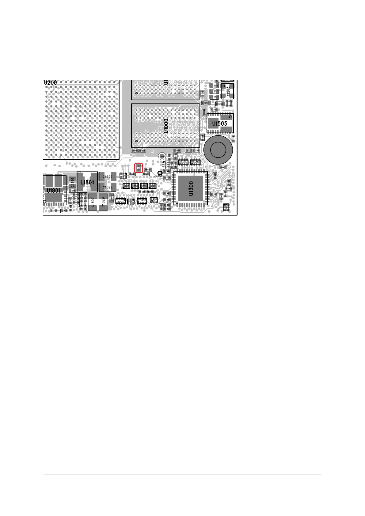
• Short-circuit R235 (see Figure 17) while powering-up the module (in order to sample the MPSoC boot
selection pins correctly for JTAG boot mode)
Figure 17: JTAG Boot Mode Resistor - Assembly Drawing Top View (lower right part) for Revision 4 Modules
3.7 eMMC Boot Mode
In the eMMC boot mode, the PS boots from the eMMC flash located on the module. The flash device is
connected to the PS MIO pins 13-22 for 8-bit data transfer mode.
3.8 QSPI Boot Mode
In the QSPI boot mode, the PS boots from the QSPI flash located on the module. The flash device is
connected to the PS MIO pins 0-5.
3.9 SD Card Boot Mode
In the SD card boot mode the PS boots from the SD card located on the base board. There are two SD card
boot modes available on the Mercury+ XU1 SoC module. Please note that the SD boot mode with level
shifter is currently not supported.
The SD boot mode with level shifter is used with Ultra High Speed (UHS) SD cards. The controller will start
the communication at 3.3 V and afterwards it will command the card to drop from 3.3 V operation to 1.8
V operation. For this mode, an external SD 3.0 compliant level shifter is required. This boot mode may be
supported in the future by Enclustra modules and base boards.
D-0000-428-001 54 / 66 Version 13, 15.08.2019
 Loading...


