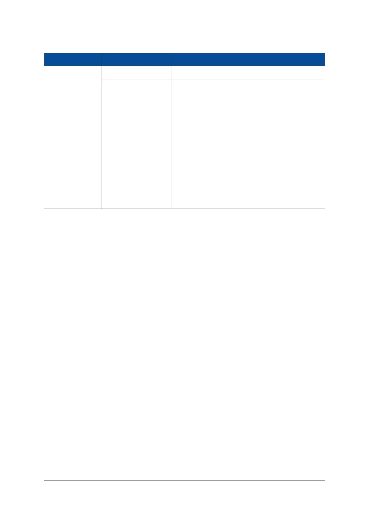
Pin Number Signal Name Description
16 TRACE_EN# Trace interface enable signal
18 TRACE_CLK
22 TRACE_CTL
Debug trace interface
23 TRACE_DQ0
(Refer to Zynq UltraScale+ MPSoC Technical
24 TRACE_DQ4
Reference Manual [19])
25 TRACE_DQ1
26 TRACE_DQ5
27 TRACE_DQ2
28 TRACE_DQ6
29 TRACE_DQ3
30 TRACE_DQ7
Table 36: Debug Connector Interface - Revision 1 and 2 Modules
The trace signals can be used to debug the processor running at full speed, allowing the user to collect
information on the CPU instruction execution and data transfers.
In order to enable the trace interface, TRACE_EN# signal must be pulled low from the debug connector, and
MIO pins 0-9 must be assigned to TRACE controller in the PS settings of the Vivado project. Additionally,
starting with revision 2 modules, the trace clock multiplexer must be equipped. Refer to the Mercury+ XU1
SoC Module User Schematics [6] for details.
D-0000-428-001 48 / 66 Version 13, 15.08.2019
 Loading...


