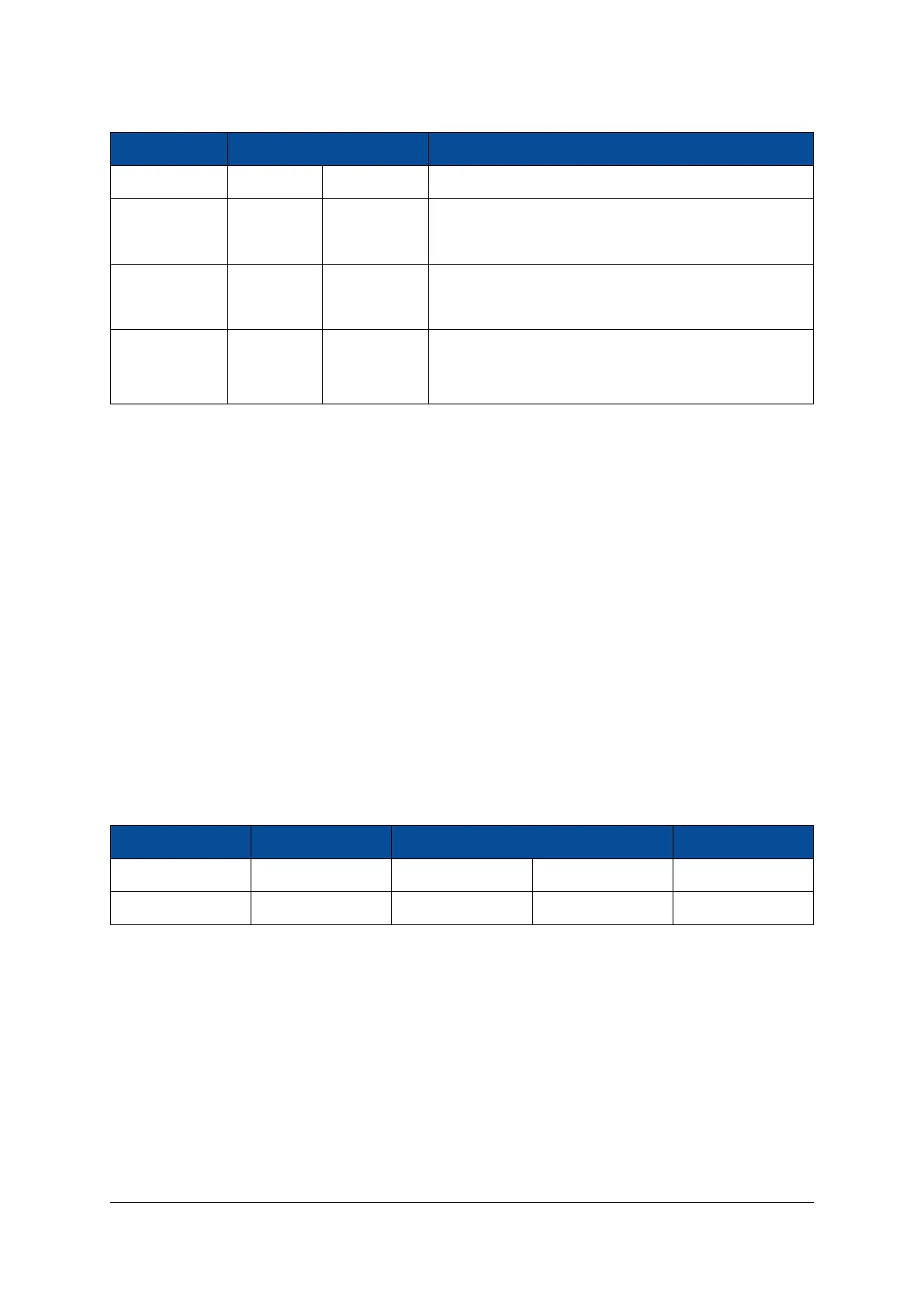
Signal Name Frequency Package Pin MPSoC Pin Type
CLK33 33.33 MHz P20 PS_REF_CLK
CLK27_GTR_P
27 MHz
H25 PS_MGTREFCLK3P_505
CLK27_GTR_N H26 PS_MGTREFCLK3N_505
CLK100_GTR_P
100 MHz
K25 PS_MGTREFCLK2P_505
CLK100_GTR_N K26 PS_MGTREFCLK2N_505
PS_PADI
32.768 kHz
R22 PS_PADI (crystal pad input for MPSoC built-in RTC)
PS_PADO R23 PS_PADO (crystal pad output for MPSoC built-in RTC)
Table 21: Module Clock Resources
2.13 Reset
The power-on reset signal (POR) and the PS system reset signal (SRST) of the MPSoC device are available
on the module connector.
Pulling PS_POR# low resets the MPSoC device, the Ethernet and the USB PHYs, and the QSPI and eMMC
flash devices. Please refer to the Enclustra Module Pin Connection Guidelines [11] for general rules regarding
the connection of reset pins.
Pulling PS_SRST# low resets the MPSoC device and enables the connection between QSPI flash and module
connector, allowing the flash to be programmed from an external SPI master.
For details on the functions of the PS_POR_B and PS_SRST_B signals refer to the Zynq UltraScale+ MPSoC
Technical Reference Manual [19].
Table 22 presents the available reset signals. Both signals, PS_POR# and PS_SRST#, have on-board 10 kΩ
pull-up resistors to VCC_CFG_MIO. For on-board devices using 1.8 V signaling, a PS_POR# low voltage variant
is generated (PS_POR#_LV).
Signal Name Connector Pin Package Pin FPGA Pin Type Description
PS_POR# A-132 U23 PS_POR_B Power-on reset
PS_SRST# A-124 P19 PS_SRST_B System reset
Table 22: Reset Resources
Please note that PS_POR# is automatically asserted if PWR_GOOD is low.
2.14 LEDs
There are three active-low user LEDs on the Mercury+ XU1 SoC module - two of them are connected to the
PS and one is connected to the PL.
The PS LED signals are shared with the debug connector trace signals on modules revisions 1 and 2.
On revision 1 modules, LED1# is connected to both PS and PL, while LED2# is mapped to a different FPGA
pin. Also, an additional LED signal, LED3#, is available on revision 1 modules on package pin Y7. For details,
D-0000-428-001 36 / 66 Version 13, 15.08.2019
 Loading...


