EasyManua.ls Logo

Enclustra Mercury+ XU1 User Manual

Default Icon
66 pages
To Next Page IconTo Next Page
To Previous Page IconTo Previous Page
Page #10 background image
2 Module Description
2.1 Block Diagram
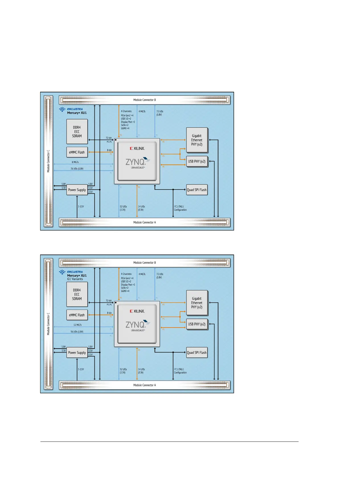
Figure 1: Hardware Block Diagram
Figure 2: Hardware Block Diagram - G1 Variants
The main component of the Mercury+ XU1 SoC module is the Xilinx Zynq Ultrascale+ MPSoC device. Most
of its I/O pins are connected to the Mercury+ module connector, making up to 214 regular user I/Os avail-
able to the user. Further, up to twenty MGT pairs are available on the module connector, making possible the
D-0000-428-001 10 / 66 Version 13, 15.08.2019

Table of Contents

Question and Answer IconNeed help?

Do you have a question about the Enclustra Mercury+ XU1 and is the answer not in the manual?

Enclustra Mercury+ XU1 Specifications

General IconGeneral
BrandEnclustra
ModelMercury+ XU1
CategoryControl Unit
LanguageEnglish

Summary

Overview of Mercury+ XU1 SoC Module

Safety and Warnings

Safety, ESD, and EMC guidelines for module handling and operation.

Module Features

Detailed list of hardware specifications and capabilities of the Mercury+ XU1 SoC module.

Deliverables and Accessories

Items included with the module and available supporting resources like reference designs.

Xilinx Tool Support

Information on the required Vivado Design Edition software for MPSoC device support.

Module Description

Block Diagram

Visual representation of the Mercury+ XU1 SoC module's hardware architecture and connectivity.

Product Configuration and Codes

Explains product code structure and lists standard module configurations and their specifications.

Module Connector and Pinout

Details on physical connectors, pin assignments, and user I/O bank information.

I/O System Details

Comprehensive details on I/O banks, voltage usage, signal terminations, and pin configurations.

High-Speed Transceivers (MGT)

Description of GTH and GTR transceivers, their configurations, and capabilities for high-speed interfaces.

Power Management and Supplies

How power is generated, controlled, supplied, monitored, and safety considerations.

Memory and Storage Devices

Specifications and configurations for DDR4 SDRAM, QSPI flash, and eMMC flash memory.

Communication Interfaces

Details on Gigabit Ethernet, USB 2.0/3.0, and SD Card interfaces and their configurations.

System Clocks and Reset

Module clock resources and system reset signals (POR, SRST) for MPSoC initialization.

Device Configuration

Configuration Signals

Key signals for MPSoC configuration, including boot mode selection and flash programming.

Boot Modes

Supported boot modes (eMMC, QSPI, SD Card, JTAG) and their configuration requirements.

JTAG and Debugging

Using JTAG for PL/PS access, debugging, and programming via module connector or debug connector.

Flash Programming Methods

Methods for programming eMMC and QSPI flash memory using various interfaces and tools.

I2C Communication

I2C Interface Overview

Details on the I2C bus connection, speed limits, and signal descriptions.

EEPROM Configuration and Memory Map

Information on the secure EEPROM, its memory map, and storage of module configuration data.

Operating Conditions

Absolute Maximum Ratings

Specifies the extreme voltage and temperature limits for the module to prevent damage.

Recommended Operating Conditions

Outlines the voltage and temperature ranges for safe and reliable operation of the module.

Ordering and Support

Ordering Information

Instructions for ordering the module and requesting product information from Enclustra.

Technical Support

Guidance on how to access technical support resources and assistance from Enclustra.

Related product manuals