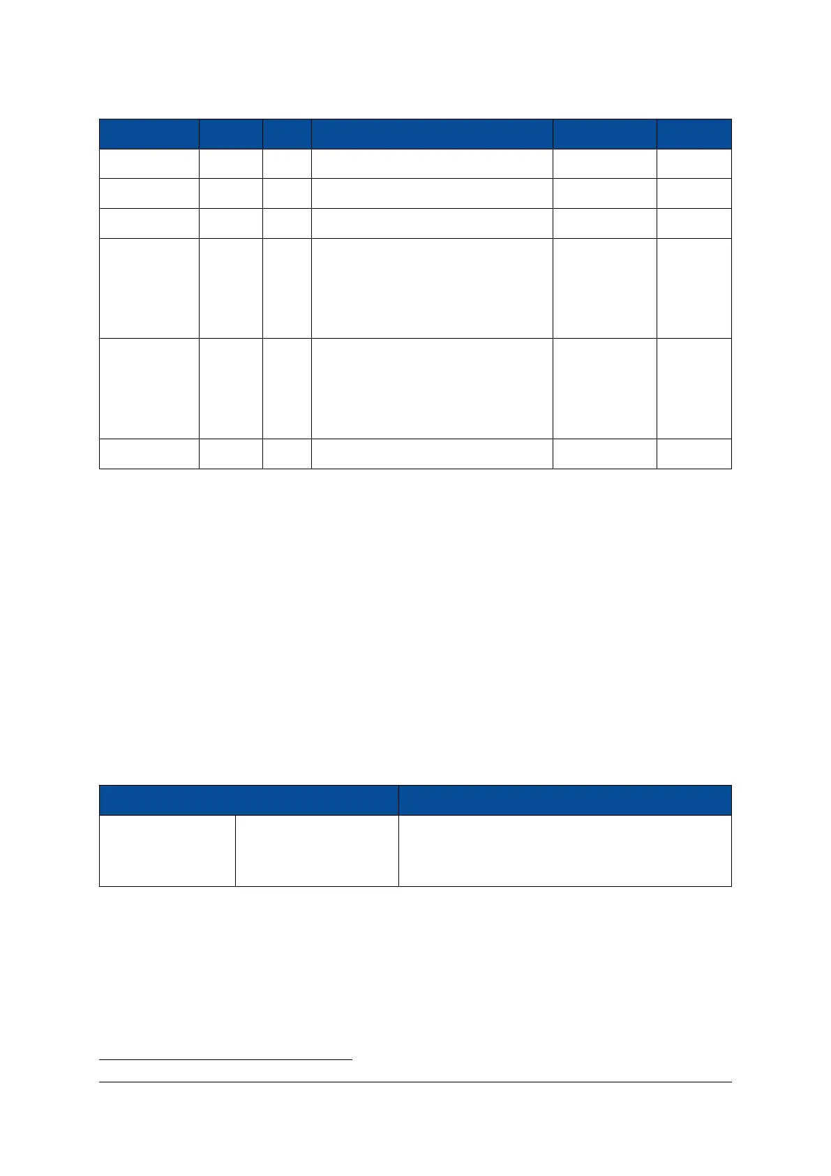
Signal Name Signals Pairs Differential Single-ended I/O Bank
IO_B64_<...> 52 24 In/Out In/Out 64 (HP)
1
IO_B65_<...> 50 24 In/Out In/Out 65 (HP)
1
IO_B66_<...> 50 24 In/Out In/Out 66 (HP)
1
IO_B47_<...> 24 12 In/Out (no LVDS/LVPECL outputs sup-
ported; internal differential termina-
tion not supported)
In/Out 47 (HD)
1
Refer to Section 2.9.3 for details.
IO_B48_<...> 24 12 In/Out (no LVDS/LVPECL outputs sup-
ported; internal differential termina-
tion not supported)
In/Out 48 (HD)
1
Refer to Section 2.9.3 for details.
Total 200 96 - - -
Table 5: User I/Os
Please note that on the “G1” variants with 16 GTH transceivers, not all I/Os listed in Table 5 are available on
the module connector. Certain user I/Os on the module connectors can be connected to various MPSoC
I/Os, depending on the product variant. Section 2.9.2 lists and describes the connectivity for these pins for
each assembly variant. The multi-use signals on the module connector are not named according to the
naming convention described above.
The multi-gigabit transceiver (MGT) are described in section 2.10.
2.9.2 I/O Pin Exceptions
The I/O pin exceptions are pins with special functions or restrictions (for example, when used in combination
with certain Mercury boards they may have a specific role).
PCIe Reset Signal (PERST#)
Table 6 lists the I/O pin exceptions on the Mercury+ XU1 SoC module related to the PCIe reset connection.
I/O Name Module Connector Pin Description
PS_MIO42_PERST# A-104 When the pin has a low value, ETH0_TXD3_PERST# pin
(MIO30) is pulled to ground via a 1 kΩ resistor for PCIe
PERST# connection implementation
Table 6: I/O Pin Exceptions - PERST#
When the Mercury+ XU1 SoC module is used in combination with a Mercury+ PE1 base board as a PCIe
device, the low value of the PERST# signal coming from the PCIe edge connector on the module connector
pin A-104 (PS_MIO42_PERST#) pulls the ETH0_TXD3_PERST# (MIO30) to ground via a 1 kΩ resistor.
MIO30 is the default pin used for the reset signal of the PCIe PS built-in block, therefore it was chosen for
the reset implementation. The Ethernet controller 0 is disabled when the PCIe hard block is used; note that
any other valid position for PERST# would have resulted in having the Ethernet controller disabled.
1
HD = high density pins, HP = high performance pins; Refer to the Zynq UltraScale+ MPSoC Overview [23] for details.
D-0000-428-001 20 / 66 Version 13, 15.08.2019
 Loading...


