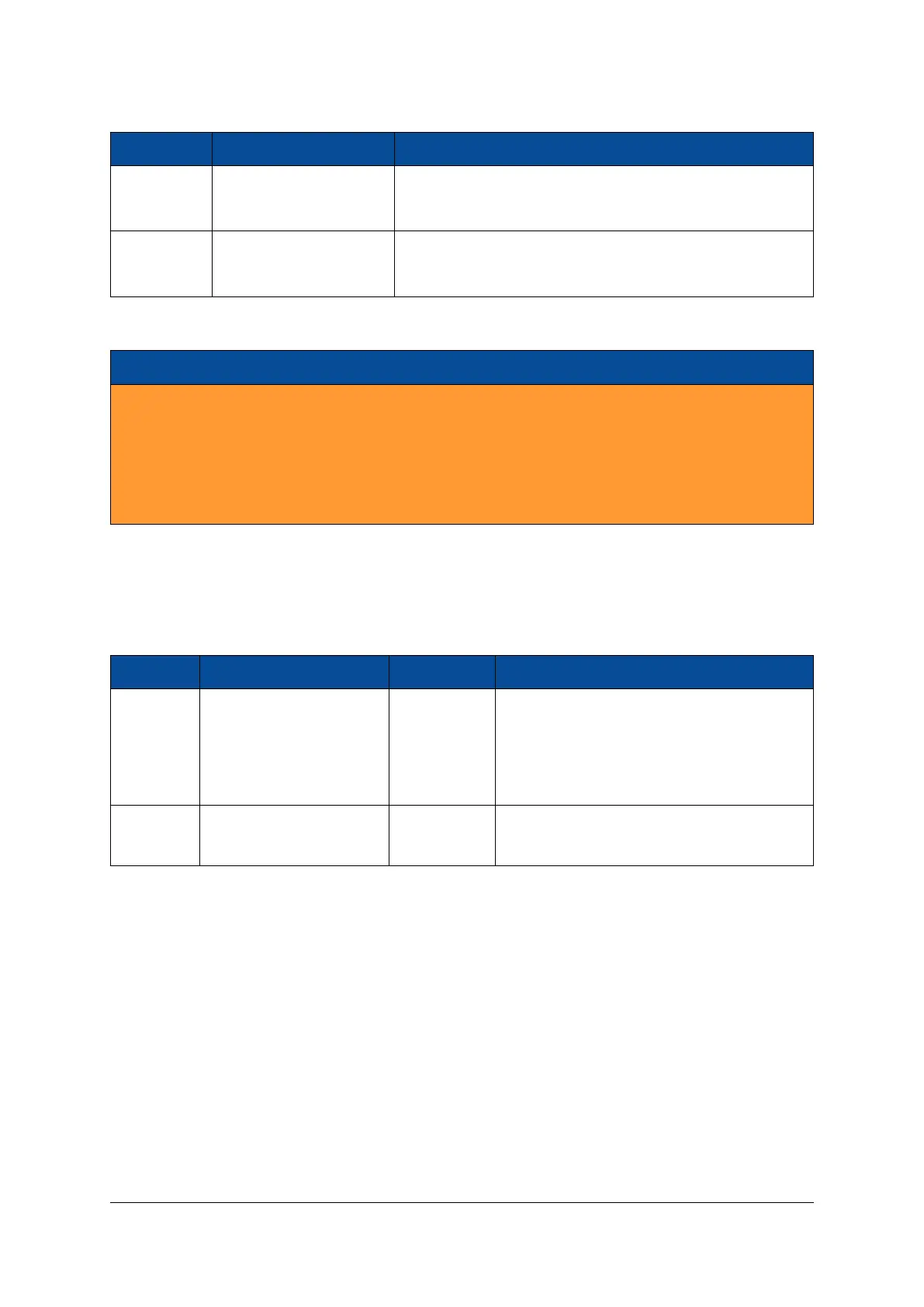
Pin Name Module Connector Pin Remarks
PWR_EN A-10
Floating/3.3 V: Module power enabled
Driven low: Module power disabled
PWR_GOOD A-12
0 V: Module supply not ok
3.3 V: Module supply ok
Table 16: Module Power Status and Control Pins
Warning!
Do not apply any other voltages to the PWR_EN pin than 3.3 V or GND, as this may damage the Mer-
cury+ XU1 SoC module. PWR_EN pin can be left unconnected.
Do not power the VCC_IO pins (for example by connecting VCC_3V3 to VCC_IO directly) if PWR_EN is
used to disable the module. In this case, VCC_IO needs to be switched off in the manner indicated in
Figure 13.
2.11.3 Voltage Supply Inputs
Table 17 describes the power supply inputs on the Mercury+ XU1 SoC module. The VCC voltages used as
supplies for the I/O banks are described in Section 2.9.5.
Pin Name Module Connector Pins Voltage Description
VCC_MOD A-1, 2, 3, 4, 5, 6, 7, 8, 9, 11 5 - 15 V ±5% Supply for 0.72/0.85/0.9 V, 0.85/0.9 V, 0.9 V,
1.2 V, 1.8 V, 3.3 V and 5.0 V voltage regulators.
The 2.5 V supply is generated from the 3.3 V
supply. The input current is rated at 3 A (0.3
A per connector pin).
VCC_BAT A-168 2.7 - 3.6 V Battery voltage for MPSoC battery-backed
RAM and battery-backed RTC
Table 17: Voltage Supply Inputs
2.11.4 Voltage Supply Outputs
Table 18 presents the supply voltages generated on the Mercury+ XU1 SoC module, that are available on
the module connector.
D-0000-428-001 33 / 66 Version 13, 15.08.2019
 Loading...


