PHY Type Manufacturer Type
KSZ9031RNX Microchip (Micrel) 10/100/1000 Mbit
Table 29: Gigabit Ethernet PHYs Type
2.19.2 Signal Description
PHY 0 is connected to ETH 0 controller from the PS I/O bank 501. One of the Ethernet TX data signals is
shared with the PCIe reset signal (PERST#); if the application requires a hard PCIe block, the ETH 0 interface
is not available. Refer to Section 2.9.2 for details on the PERST# connection.
Warning!
Gigabit Ethernet 0 interface is not available when the PCIe endpoint in the PS is used (because of the
PERST# connection).
PHY 1 is connected to ETH 3 controller from the PS bank 502. The corresponding MIO signals (64-75) are
shared between Ethernet PHY 1 and USB PHY 1, therefore only one of them can be used. By default the
Ethernet connection is enabled.
Warning!
Gigabit Ethernet 1 interface is not available when USB 1 interface is active.
USB1_RST#_ETH1_RST is pulled to GND via a 1 kΩ resistor; to release the USB PHY from reset, this signal
must be driven high from MIO23. ETH1_RST# is pulled to 1.8 V via a 10 kΩ resistor; if USB1_RST#_ETH1_RST
signal is driven high from the PS, the Ethernet reset is connected to GND.
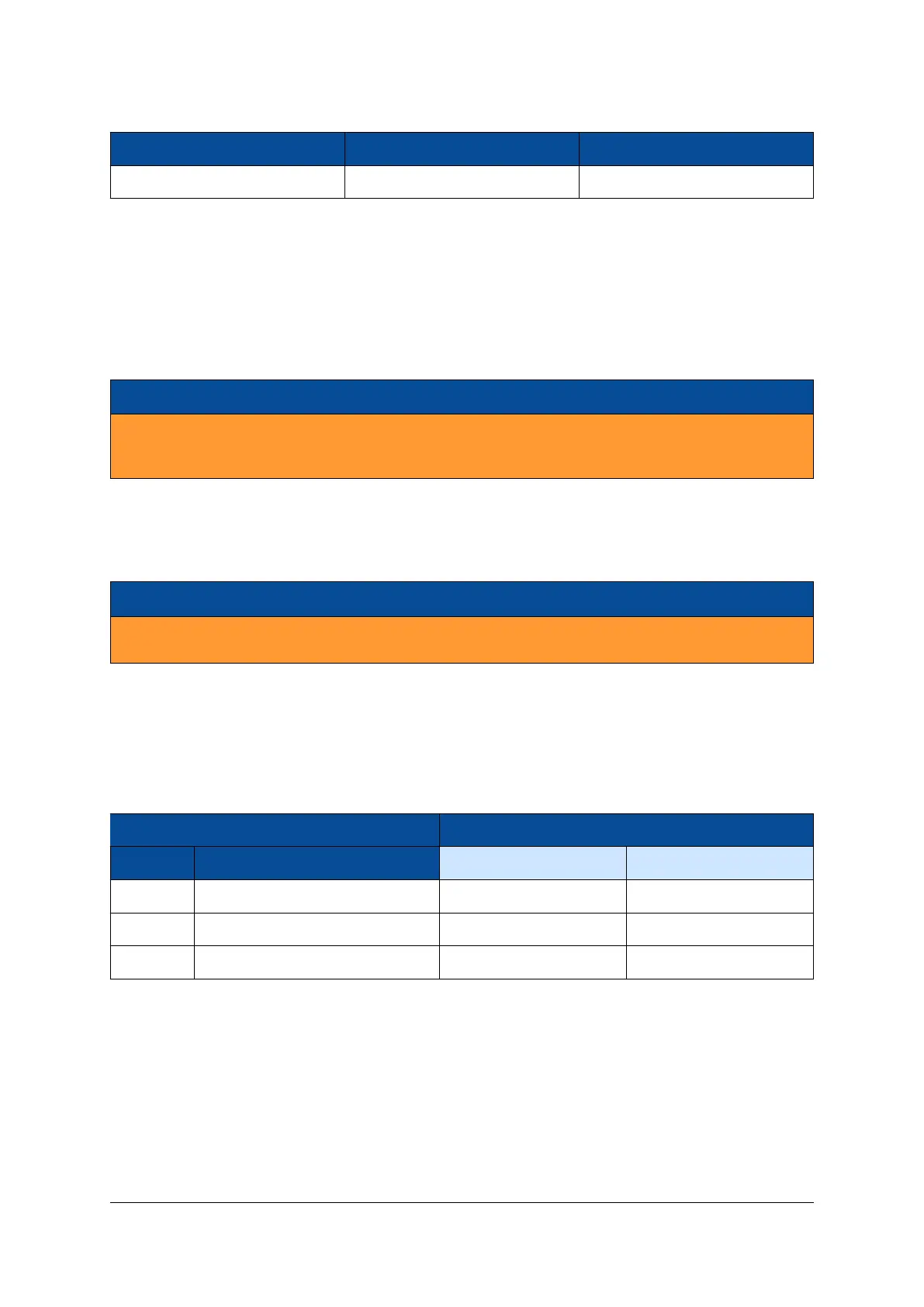
Both reset signals (for Ethernet and USB) are pulled to GND if the PS_POR# is active. Table 30 describes the
behavior of the USB1/ETH1 selection circuit; the default selection is marked in bold.
Condition Function
PS_POR# USB1_RST#_ETH1_RST (MIO23) USB PHY 1 Ethernet PHY 1
0 - In reset In reset
1 0 In reset Active
1 1 Active In reset
Table 30: USB1/ETH1 Selection
The two Gigabit Ethernet PHYs have a shared MDIO interface and a shared interrupt line. The interrupt
output of the Ethernet PHYs is connected to the I2C interrupt line, available on MIO pin 12.
D-0000-428-001 42 / 66 Version 13, 15.08.2019
 Loading...


